Method for achieving holographic waveguide grating large exit pupil

A holographic waveguide and grating technology, applied in the field of holographic waveguide grating, can solve the problems of energy loss and low diffraction efficiency of holographic grating

Inactive Publication Date: 2015-01-14
郑敏
View PDF4 Cites 13 Cited by
  • Summary
  • Abstract
  • Description
  • Claims
  • Application Information

AI Technical Summary

Problems solved by technology

For example, the holographic waveguide shows the utilization rate of light energy by the grating in the glasses. Due to the low diffraction efficiency of the holographic grating, the coupling in and out of light waves will be accompanied by energy loss.

Method used


Image

  • Method for achieving holographic waveguide grating large exit pupil
  • Method for achieving holographic waveguide grating large exit pupil
  • Method for achieving holographic waveguide grating large exit pupil

Examples


Embodiment

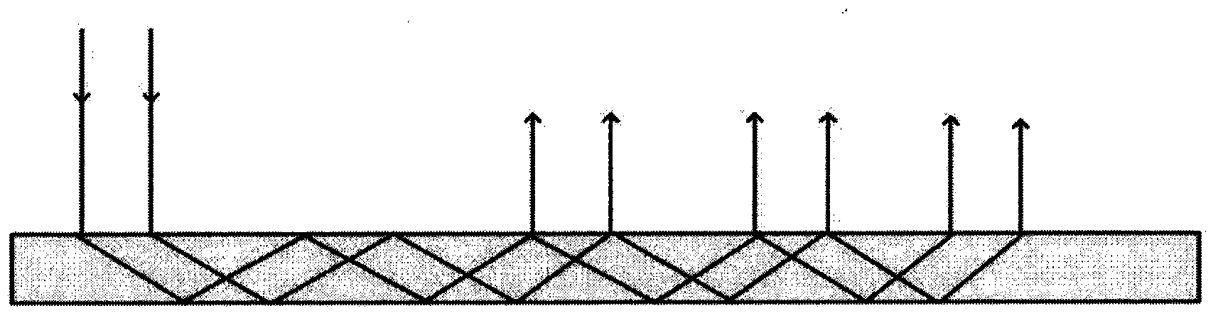
[0036] The method for realizing the large exit pupil of the holographic waveguide grating disclosed in this embodiment is realized by the micro display part, the collimating lens part and the holographic waveguide grating part, and the interference modulation method is used to modulate different lights in different regions on a designated plane. The strong light wave interferes with another plane wave, and the same grating with different diffraction efficiency can be fabricated at the same time, so as to realize the uniform diffraction and output of the light wave, and then realize the large exit pupil of the holographic waveguide grating.

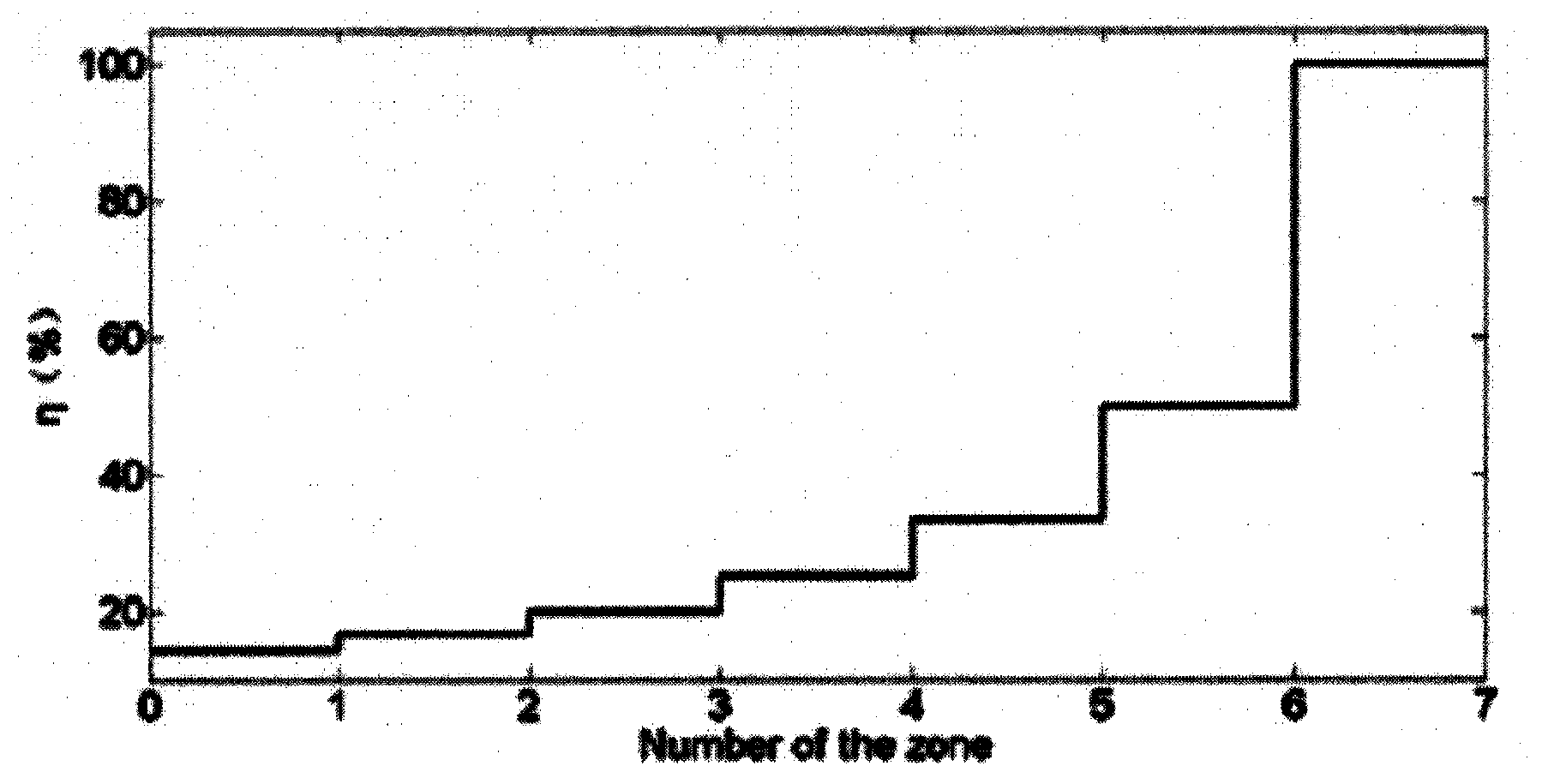
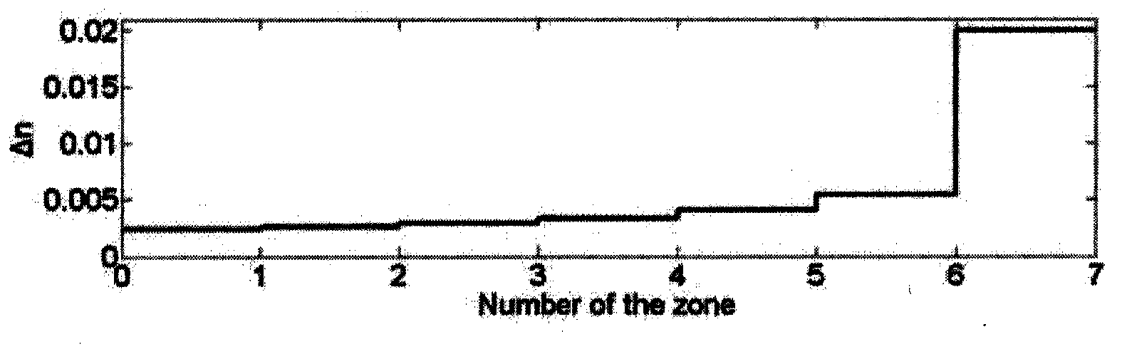
[0037] like figure 1 As shown, in order to make the holographic waveguide grating have the property of a large exit pupil, the main problem is to make the light intensity of the multiple total reflection coupling and output uniform, so that the diffraction efficiency of each coupling output needs to be different. With the fabrication metho...


PUM


Abstract

The invention provides a method for achieving a holographic waveguide grating large exit pupil. The holographic waveguide grating large exit pupil is achieved through a micro display part, a collimating lens part and a holographic waveguide grating part. Light waves which have different light intensities in different areas are modulated in a specified plane by means of the interference modulation method. The light waves interfere with a plane wave beam, and the same grating with different diffraction efficiencies is manufactured at the same time, so that uniform diffraction and exit of the light waves are achieved, and then the holographic waveguide grating large exit pupil is achieved. The method is used for designing diffraction optical elements of any structures, and the feasibility of the method is verified through experiments. The method is used for manufacturing a holographic grating which has different diffraction efficiencies in different areas, and therefore uniform-exit large exit pupil holographic waveguide imaging is achieved.

Description

technical field [0001] The invention relates to a method for realizing a holographic waveguide grating, in particular to a method for realizing a large exit pupil of a holographic waveguide grating, and belongs to the field of holographic waveguide grating. Background technique [0002] At the beginning of the 20th century, for the needs of the Air Force aiming in combat, an aiming ring with a front sight was installed on the aircraft for aiming, similar to the simple aiming system on the early rifle. The three-point line is the earliest quasi-head-up sight. How the display works. Later, in order to reduce the pilot's sighting burden, other sighting systems, including the Ortiz sight, were installed on the aircraft. In fact, the hand-held monocular was installed on the aircraft, allowing the pilot to aim and use it. In the early days of World War II, sight-seeing reflex sights and servo halo gyro sights began to appear one after another, mainly composed of a halo deflection...

Claims


Application Information

Patent Timeline
Patent Type & Authority Applications(China)
IPC IPC(8): G02B27/44G02B6/34G03H1/02
CPCG02B27/44G02B6/34G03H1/02
Inventor 郑敏
Owner 郑敏
Why Eureka
Try Eureka