Traction converter and railway vehicle

A power conversion device and power conversion circuit technology, which is applied in the modification of power electronics, output power conversion devices, electric locomotives, etc., can solve the problems of increasing the number of sheets, the weight of the cooler, and the inability to achieve uniform temperature, etc., to achieve uniform temperature effect

Active Publication Date: 2015-01-14
HITACHI LTD
View PDF8 Cites 3 Cited by
  • Summary
  • Abstract
  • Description
  • Claims
  • Application Information

AI Technical Summary

Problems solved by technology

[0009] In the cooler described in Patent Document 1, the pitch of fins on the upper side, that is, the leeward side is reduced and the number of fins is increased. However, in terms of this structure, the areas of the fins on the upwind side and the leeward side are not optimal. Therefore, there are problems such as uneven temperature of each semiconductor element and poor cooling efficiency.
[0010] In addition, in the cooler described in Patent Document 2, when the fin group is divided into three, for example, the division point between the windward fin and the middle fin and the division point between the midstream fin and the leeward fin The area occupied by the fins on the windward side where the fins are divided into three equal parts along the cooling air flow direction, that is, the fins on the downwind side with a smaller pitch and a large number of fins, increases the weight of the cooler. subject
Furthermore, the structure described in Patent Document 2 is effective at a specific fin pitch, but there is a problem that the temperature cannot be made uniform when the fin pitch is changed.
Furthermore, the fins on the windward side, midstream, and leeward side are not in the same shape, so there is another problem of high manufacturing cost.

Method used


Image

  • Traction converter and railway vehicle
  • Traction converter and railway vehicle
  • Traction converter and railway vehicle

Examples


Embodiment 1

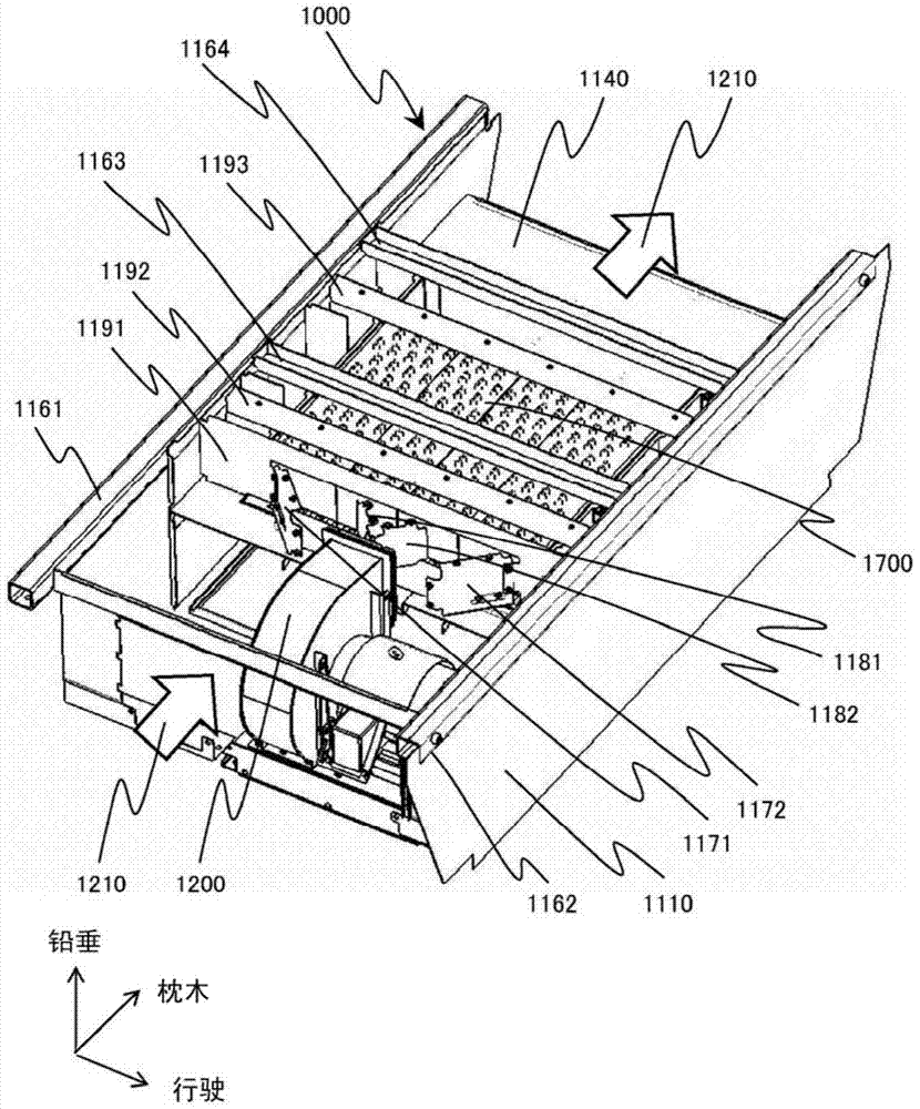
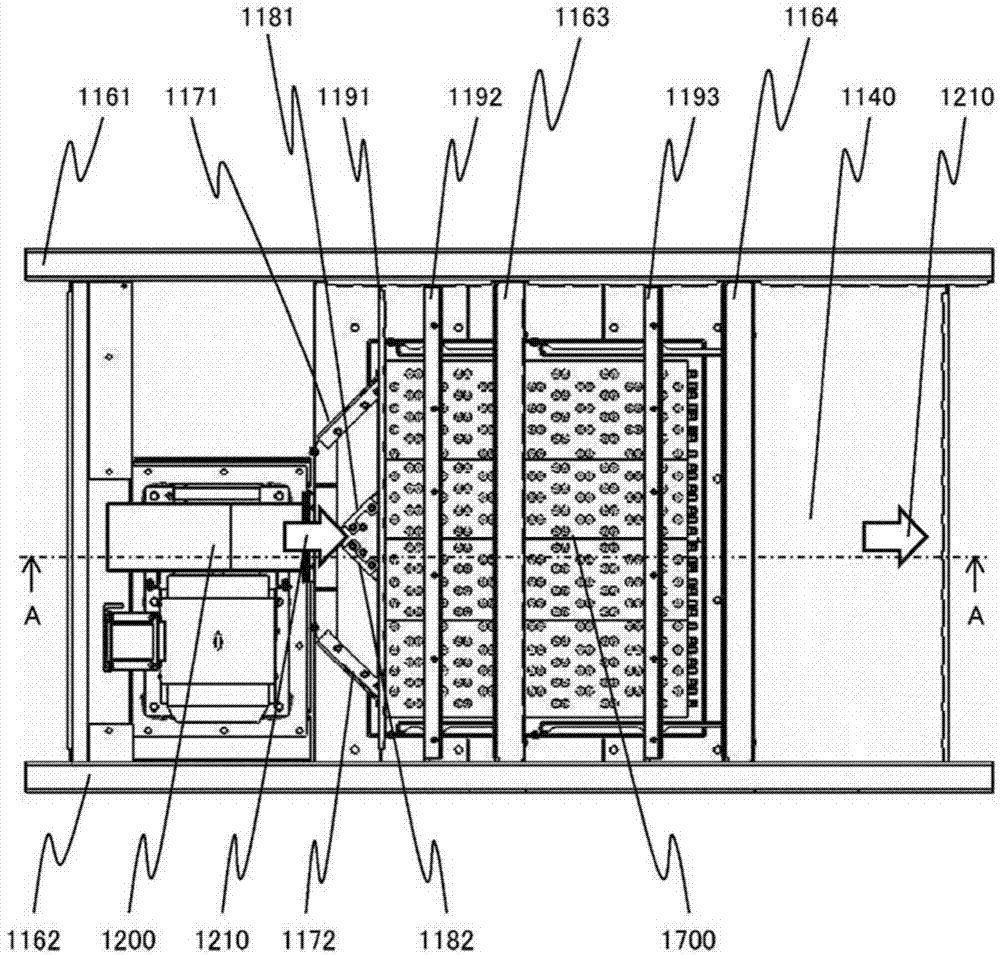
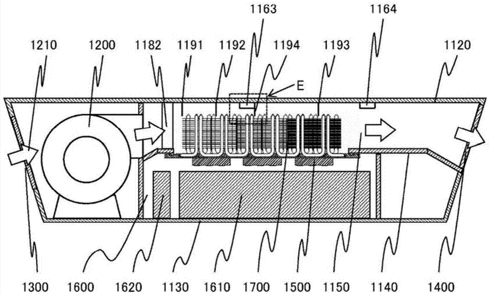
[0095] Hereinafter, the power conversion device of the present invention will be described in detail with reference to the drawings. figure 1 is a perspective view showing the overall configuration of the power conversion device according to the first embodiment of the present invention, figure 2 express figure 1 top view of image 3 express figure 2 A-A cutaway view.

[0096] The power conversion device 1000 is composed of a side plate 1110 , a top plate 1120 , and a bottom plate 1130 . In addition, sleeper direction beams 1161 and 1162 and travel direction beams 1163 and 1164 are provided on the upper surface of the power conversion device 1000 to secure the strength of the power conversion device 1000 . Between the top plate 1120 and the bottom plate 1130 is provided a ventilation path bottom plate 1140 . The space surrounded by the side plate 1110 , the top plate 1120 , and the ventilation path bottom plate 1140 is the ventilation path 1150 , and the cooling air 121...

Embodiment 2

[0123] Figure 14 It is a side cross-sectional view showing a cooler mounted on a power conversion device according to a second embodiment of the present invention. In the first embodiment, the position of the split point of the cooling fins in the cooling air flow direction is fixed, and the number of fins is changed to change the surface areas of the fins in the upwind area 1752, the midstream area 1753, and the downwind area 1754. The surface area of ​​the fins can be changed by changing the position of the split point of the fins in the cooling air flow direction. In the second embodiment, the number of fins 1750 is 12, 24, and 48 from the windward side, the pitch ratio of the fins is 4:2:1, and the surface area of ​​the fins 1750 in the upwind region 1752 is It is 0.35 times of the surface area of ​​the cooling fins 1750 in the downwind area 1754, and the surface area of ​​the cooling fins 1750 in the midstream area 1753 is 0.53 times of the surface area of ​​the cooling...

Embodiment 3

[0127] Figure 16 It is a side cross-sectional view showing a cooler mounted on a power conversion device according to a third embodiment of the present invention. In the third embodiment, two semiconductor element groups 1500 are provided in the cooling air flow direction, and the area where a plurality of cooling fins are provided is divided into two, an upwind area 1752 and a downwind area 1754, along the cooling air flow direction. The number of cooling fins 1750 is 26 in the upwind area 1752 and 48 in the downwind area 1754 . That is, the surface area of ​​the cooling fins 1750 in the upwind region 1752 is 0.54 times the surface area of ​​the cooling fins 1750 in the downwind region 1754 .

[0128] In the structure in which two semiconductor element groups 1500 are installed in the cooling air flow direction as in the third embodiment of the present invention, the plurality of cooling fins 1750 are divided into two parts along the cooling air flow direction, and the cool...


PUM


Abstract

The present invention equalizes the temperatures of semiconductor elements and efficiently cools the semiconductor elements in a lightweight device configuration, by optimally combining the configurations of heat radiation fins in accordance with the configuration of the semiconductor elements. A traction converter includes plural semiconductor elements included in a traction converting circuit and a cooler to radiate heat from the plural semiconductor elements to outside air, the cooler including a heat receiving block, plural heat pipes and plural heat radiation fins, the plural semiconductor elements being arrayed on one surface of the heat receiving block, heat receiving parts of the plural heat pipes being buried in the opposite surface of the heat receiving block, heat radiation parts of the plural heat pipes being erectly provided so as to protrude from the heat receiving block, the plural heat radiation fins being joined to the heat radiation parts. In the cooler, three semiconductor elements are provided in a cooling wind flow direction, and, when a region at which the plural heat radiation fins are provided is divided in the cooling wind flow direction into three of an up-wind region, a mid-wind region and a down-wind region, a heat radiation fin surface area at the up-wind region is in a range of 0.33 to 0.42 times of a heat radiation fin surface area at the down-wind region, and a heat radiation fin surface area at the mid-wind region is in a range of 0.42 to 0.63 times of the heat radiation fin surface area at the down-wind region.

Description

technical field [0001] The present invention relates to a power conversion device, and more particularly to a power conversion device for electrified railway vehicles. Background technique [0002] Electric railway vehicles are equipped with power conversion devices such as inverters and inverters in order to control electric motors for driving the vehicles. These power conversion devices perform power conversion by switching at high frequency using semiconductor elements such as IGBT (Insulated Gate Bipolar Transistor) and GTO (Gate Turn Off Thyristor). [0003] In semiconductor elements, heat is generated during power-on and switching. If the semiconductor element becomes high temperature due to this heat, the conversion efficiency may decrease or the element may be destroyed. Therefore, it is necessary to cool the semiconductor element to a predetermined temperature. within range. Power conversion devices are mainly installed under the floor of vehicles where the mounti...

Claims


Application Information

Patent Timeline
Patent Type & Authority Applications(China)
IPC IPC(8): H02M1/00H05K7/20
CPCH01L2924/0002B61C17/12B61D17/00B61C3/00B61C17/00B61D1/00H05K7/209H05K7/20909H05K7/20009H05K7/20918H01L2924/00H05K7/20936B61D49/00B61K13/00H01L23/42H05K7/20
Inventor 安田阳介舟越砂穗田中健寺门秀一
Owner HITACHI LTD
Why Eureka
Try Eureka