Novel electric vehicle driving system

A drive system and electric vehicle technology, applied in the control system, motor generator control, AC motor control, etc., can solve problems such as low output voltage, short circuit on the input side, and failure to meet the power performance of electric vehicles

Inactive Publication Date: 2015-01-14
CHONGQING UNIV OF POSTS & TELECOMM
View PDF7 Cites 2 Cited by
  • Summary
  • Abstract
  • Description
  • Claims
  • Application Information

AI Technical Summary

Problems solved by technology

At present, the driving system of electric vehicles generally adopts the driving scheme of direct power supply and inverter, which can no longer meet the needs of the power performance of electric vehicles.
When the electric vehicle is starting, accelerating and other working conditions, the voltage of the battery will drop sharply due to the instantaneous large current discharge, the power supply voltage of the inverter will drop accordingly, and the driving torque of the electric vehicle will drop, resulting in slow acceleration and poor power performance. become worse
Traditional inverters have voltage source and current source inverters, but there are many deficiencies in traditional inverters. The main defects of voltage source inverters are as follows: 1) The upper and lower switching tubes of the same bridge arm are added The dead time causes the distortion of the output voltage; 2) The upper and lower switch tubes of the same bridge arm cannot be connected directly, otherwise it will cause a short circuit on the input side and burn the circuit: 3) The output voltage is always lower than the input voltage, which is actually a B

Method used


Image

  • Novel electric vehicle driving system
  • Novel electric vehicle driving system
  • Novel electric vehicle driving system

Examples


Embodiment Construction

[0016] The preferred embodiments of the present invention will be described in detail below in conjunction with the accompanying drawings; it should be understood that the preferred embodiments are only for illustrating the present invention, rather than limiting the protection scope of the present invention.

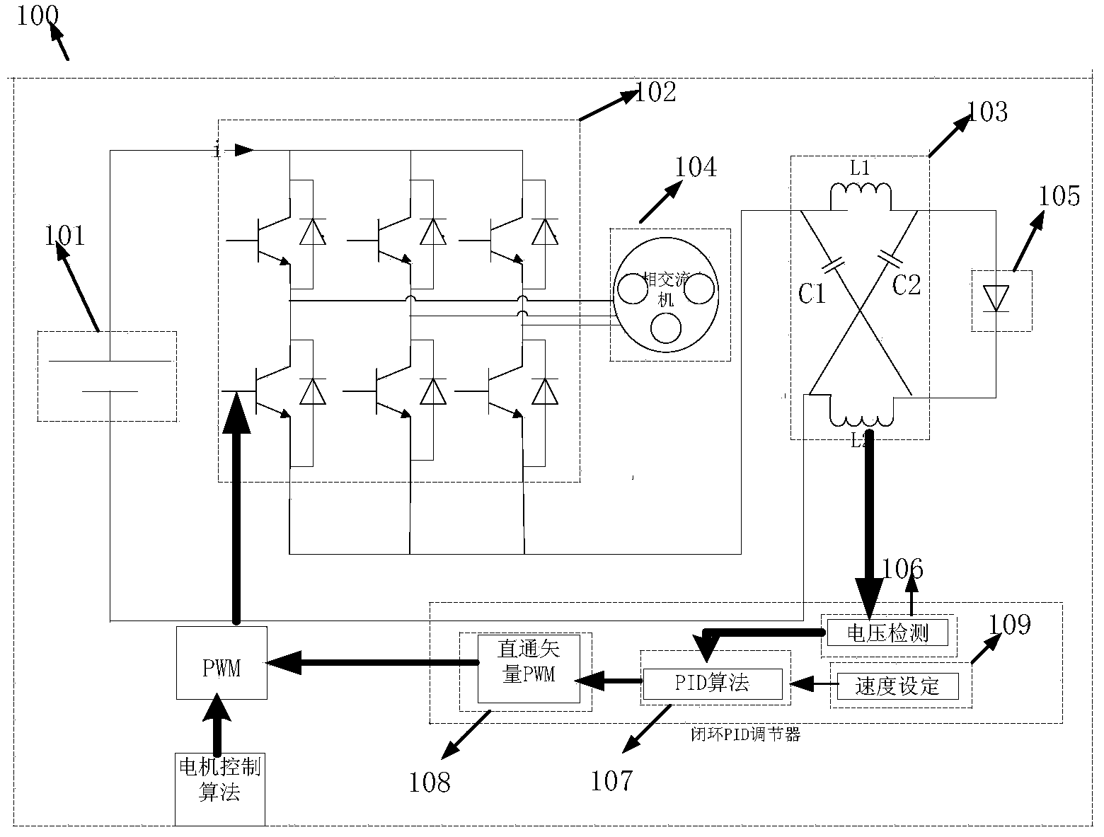
[0017] Such as figure 1 As shown, a new type of electric vehicle drive system includes a voltage closed-loop PID regulator, a Z-source inverter and a three-phase motor connected in sequence. The voltage closed-loop PID regulator is used when the DC voltage source power supply voltage is too low, By adding a direct zero vector, the input voltage of the Z-source inverter is increased, and the output voltage of the inverter is controlled; the Z-source inverter is used to convert direct current into alternating current required by a three-phase motor.

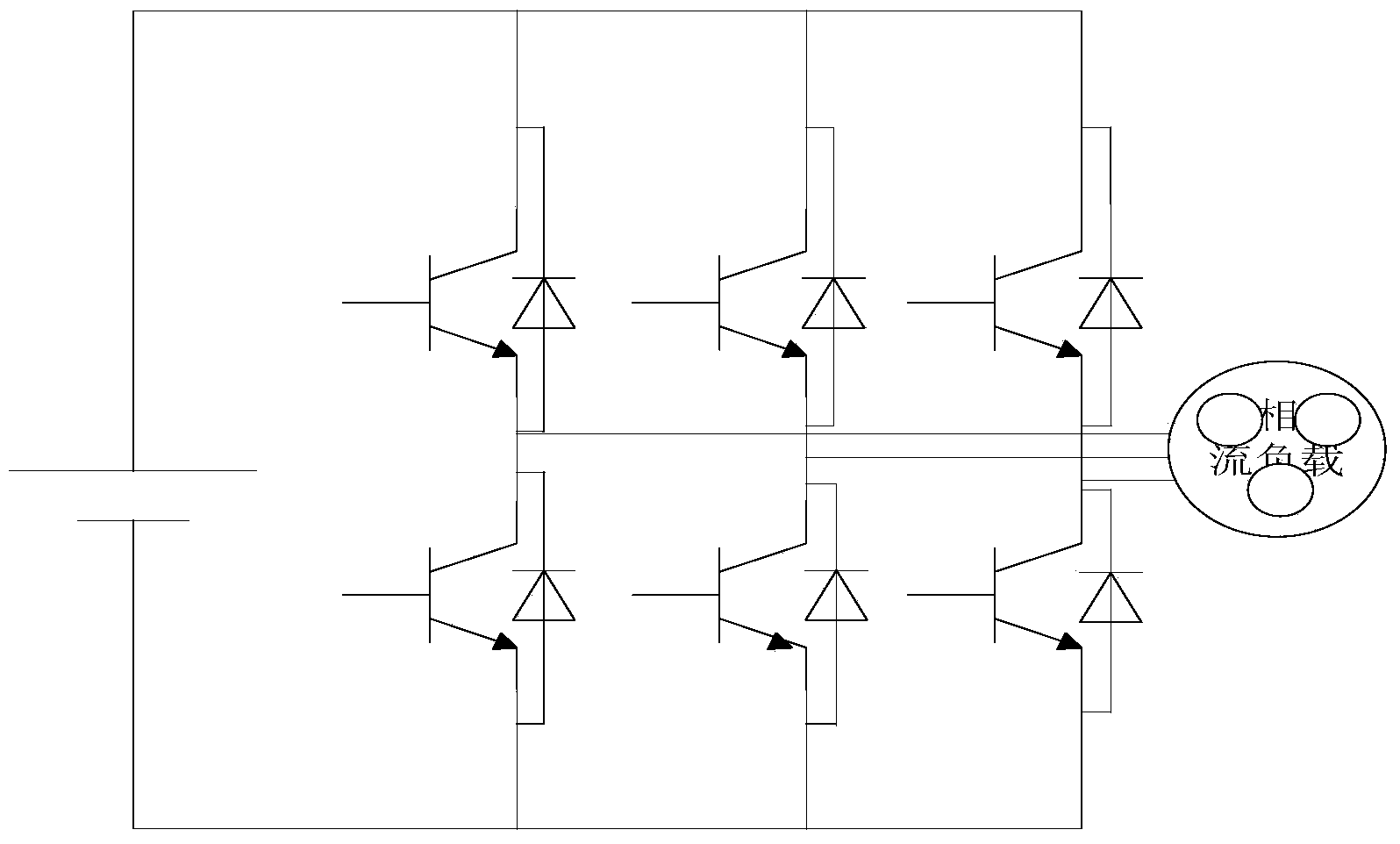
[0018] Wherein, the Z source inverter includes a DC voltage source 101, a three-phase inverter bridge 102, an X-type impe...


PUM


Abstract

The invention discloses a novel electric vehicle driving system. The system comprises a voltage closed-loop PID regulator, a Z-source inverter and a three-phase motor which are connected in sequence, wherein the voltage closed-loop PID regulator is used for increasing the input voltage of the Z-source inverter and controlling the output voltage of the inverter by adding a direct-connection zero vector when the supply voltage of a direct-current voltage source is too low, and the Z-source inverter is used for converting direct current into alternating current required by the three-phase motor. According to the system, a voltage closed loop is additionally arranged in the electric vehicle driving system while a Z-source network is introduced to increase the input voltage of the inverter and control the output voltage of the inverter by adding the direct-connection zero vector when the supply voltage of a storage battery is too low, so that the output performance of a motor driving system is improved. According to the system, the acceleration performance and power performance of an electric vehicle can be effectively improved, the efficiency of the driving system can be improved, and cost is quite low.

Description

technical field [0001] The invention relates to a power electronic converter, in particular to an electric vehicle drive system. Background technique [0002] With the popularity of the concept of energy saving and environmental protection, the research and development of electric vehicles has entered a stage of rapid development. The introduction of my country's new energy policy has provided policy support for the development of electric vehicles in my country. At present, the driving system of electric vehicles generally adopts the driving scheme of direct power supply and inverter, which can no longer meet the needs of the power performance of electric vehicles. When the electric vehicle is starting, accelerating and other working conditions, the voltage of the battery will drop sharply due to the instantaneous large current discharge, the power supply voltage of the inverter will drop accordingly, and the driving torque of the electric vehicle will drop, resulting in s...

Claims


Application Information

Patent Timeline
IPC IPC(8): H02P27/06H02M7/5387
CPCH02P27/08H02M7/53871H02M7/5395H02P2201/00
Inventor 黄智宇杜尚川陈志方彭熙夏天骏
Owner CHONGQING UNIV OF POSTS & TELECOMM
Why Eureka
Try Eureka