Biogas digester
A biogas tank and tank body technology, which is applied in the field of biogas tanks, can solve problems such as potential safety hazards of biogas waste, and achieve the effects of convenient replacement of fermentation substances or cleaning of fermentation trays, energy saving, and reduction of leakage or loss.
- Summary
- Abstract
- Description
- Claims
- Application Information
AI Technical Summary
Problems solved by technology
Method used
Image
Examples
Embodiment 1
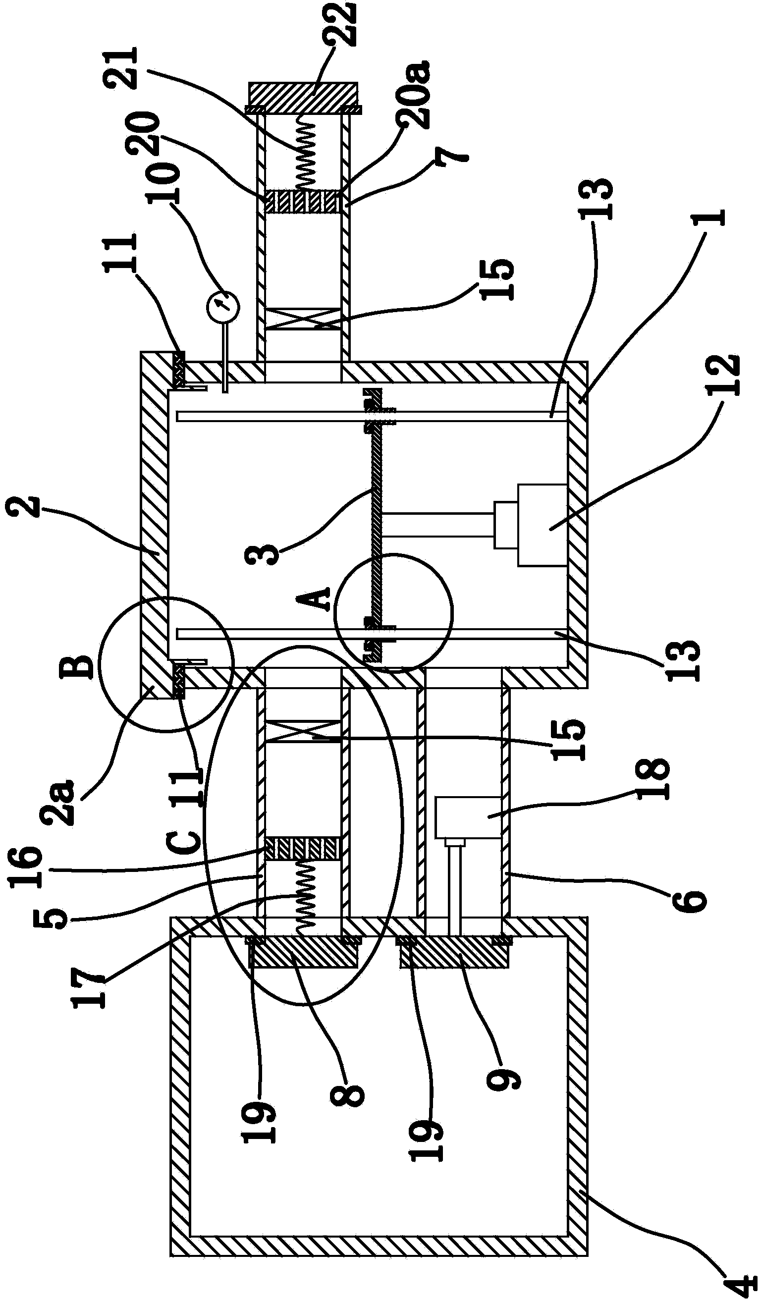
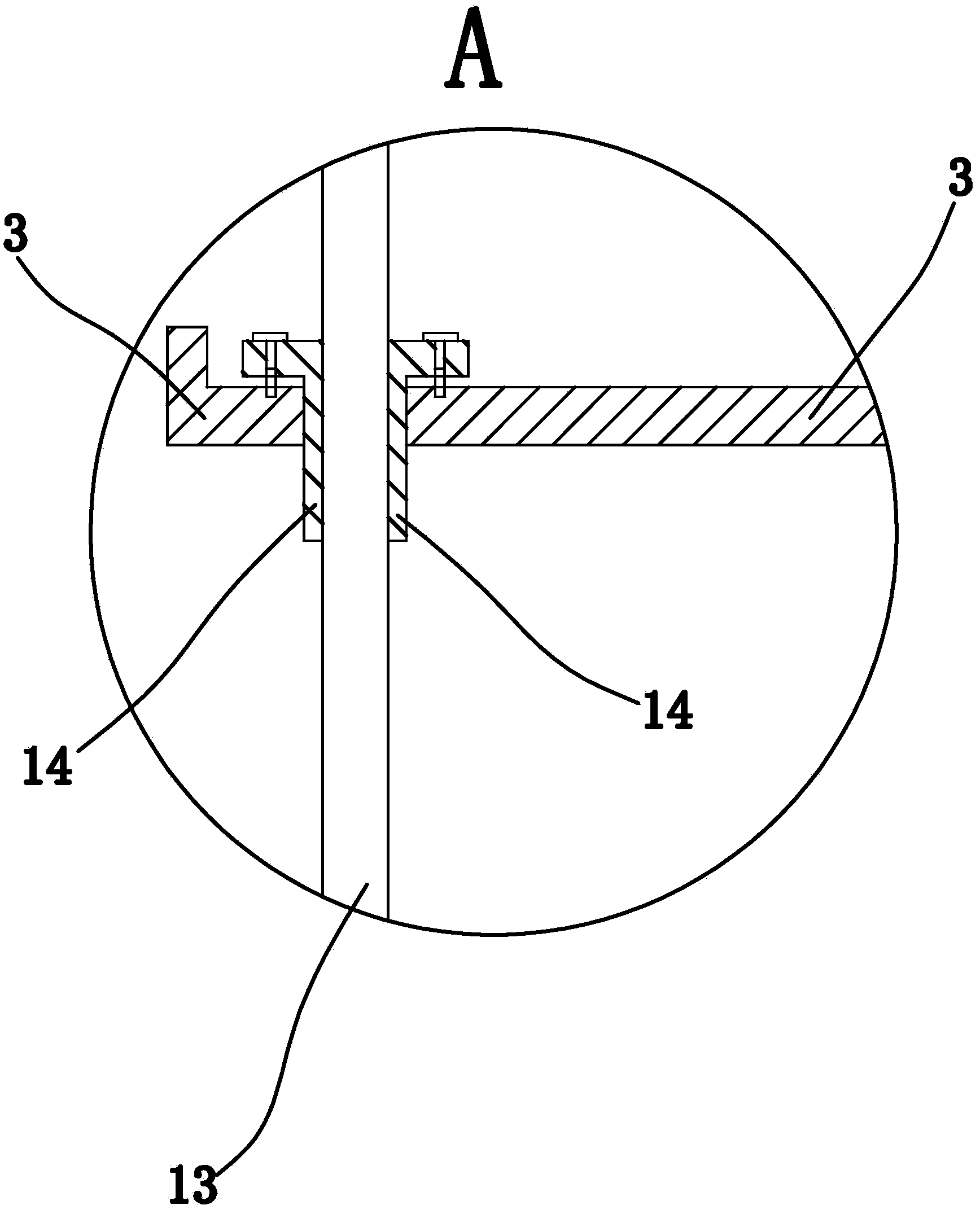
[0043] like figure 1 As shown, the biogas digester includes a pool body 1, a sealing cover 2, a fermentation plate 3, a gas storage box 4, an air inlet pipe 5, an air outlet pipe 6, an exhaust pipe 7, an elastic member, a sealing plate one 8, a sealing plate two 9, Lifting device, pressure gauge 10 and other components.
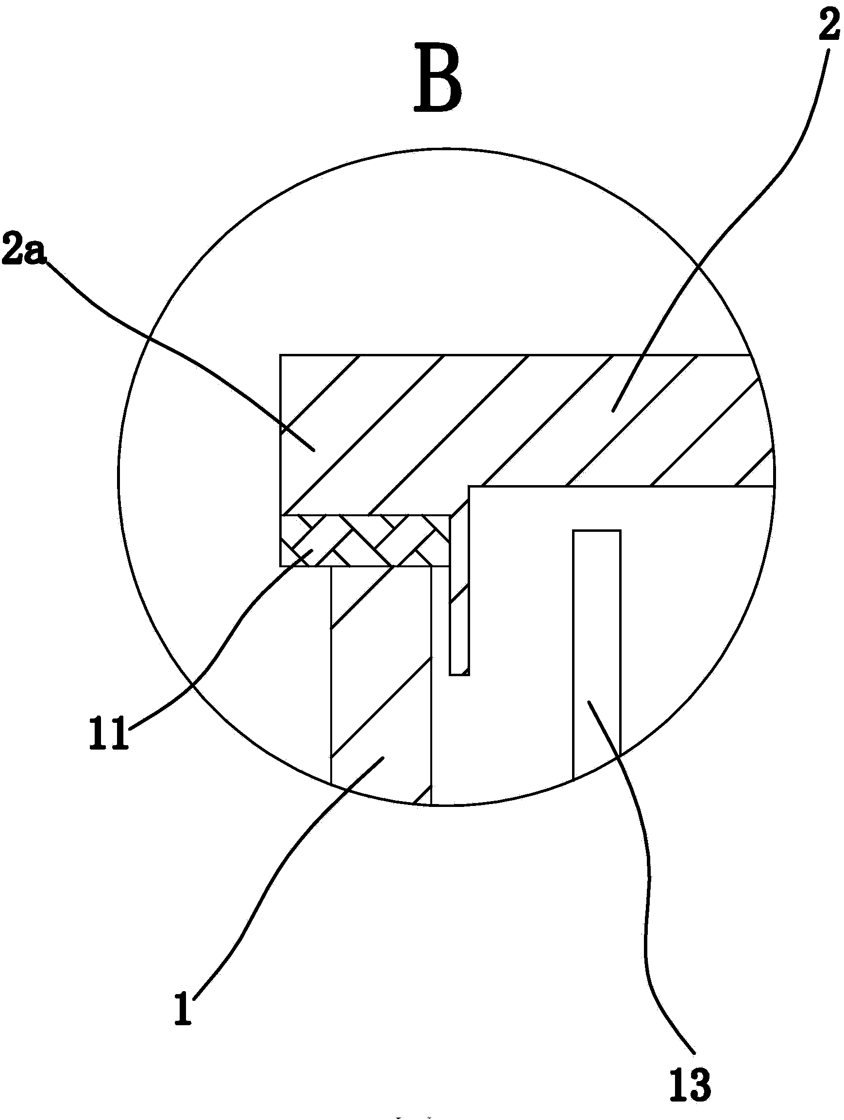
[0044] Wherein, the cell body 1 is cylindrical, and the pressure gauge 10 is fixed on the cell body 1 to measure the air pressure in the cell body 1 . The sealing cover 2 is arranged on the top of the pool body 1 and completely seals the pool body 1 . Specifically, the sealing cover 2 is cylindrical and the weight of the sealing cover 2 is much greater than the buoyancy of the biogas in the pool body 1 to the sealing cover 2, so that the sealing cover 2 will be closely attached to the top surface of the pool body 1 under the effect of weight together, so as to avoid the leakage of biogas.
[0045] Further optimization, a sealing structure is provided betwe...
Embodiment 2
[0061] The structure and principle of this second embodiment are basically the same as that of the first embodiment, except that the inner side of the sealing cover 2 has a protruding connecting portion, the outer edge of the connecting portion has an annular groove, and the sealing structure includes a The O-shaped sealing ring, and the outer peripheral surface of the O-shaped sealing ring is against the inner wall of the pool body 1 . When the sealing cover 2 is located at the top of the pool body 1, the connecting part located inside the sealing cover 2 is inserted into the pool body 1, and an O-ring is arranged between the outer side wall of the connecting part and the inner side wall of the pool body 1 to improve the sealing The tightness of the connection between the cover 2 and the pool body 1 reduces the probability of biogas leakage; at the same time, the installation of the O-ring is facilitated by setting an annular groove for placing the O-ring.
Embodiment 3
[0063] The structure and principle of the third embodiment are basically the same as those of the first embodiment, except that the lifting device includes a telescopic cylinder, and the telescopic cylinder includes a telescopic piston rod and a cylinder body fixed on the inner bottom wall of the pool body 1, and the telescopic piston rod The end portion is fixedly connected with the fermenting tray 3 by fasteners. When the telescopic cylinder works, the telescopic piston rod can translate up and down relative to the cylinder body, thereby driving the fermentation plate 3 to translate up and down; When cleaning is required, the fasteners can be unscrewed directly and the fermentation tray 3 can be removed from the telescopic piston rod, which has the advantage of being convenient for cleaning the fermentation tray 3; the fasteners can be mechanical fastening parts such as screws and bolts.
PUM
 Abstract
Description
Claims
Application Information
 - R&D
- Intellectual Property
- Life Sciences
- Materials
- Tech Scout
- Unparalleled Data Quality
- Higher Quality Content
- 60% Fewer Hallucinations
Browse by: Latest US Patents, China's latest patents, Technical Efficacy Thesaurus, Application Domain, Technology Topic, Popular Technical Reports.
© 2025 PatSnap. All rights reserved.Legal|Privacy policy|Modern Slavery Act Transparency Statement|Sitemap|About US| Contact US: help@patsnap.com


