Medium energy engine device and acting mode thereof

An engine and work-making technology, which is applied in the field of double-mass independent closed-cycle piston medium-energy engine device and its work method, and can solve problems such as safety concerns, huge engineering, and high cost

Inactive Publication Date: 2015-01-21
NINGBO HI TECH ZONE JINSHAN NEW ENERGY SCI & TECH CO LTD
View PDF4 Cites 8 Cited by
  • Summary
  • Abstract
  • Description
  • Claims
  • Application Information

AI Technical Summary

Problems solved by technology

To be clear, there are many energy methods we use for power generation. For example, some use hydropower, which is limited by geographical location and cost, the project is huge, and the cost is high; some use nuclear power to generate electricity, but we are worried about safety. ; Photovoltaic power generation is used, but limited by the cost and actual utilization rate

Method used


Image

  • Medium energy engine device and acting mode thereof
  • Medium energy engine device and acting mode thereof

Examples


Embodiment 1

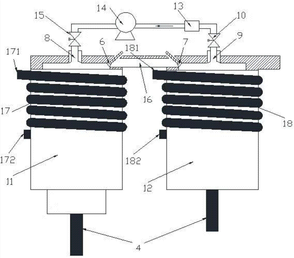
[0033] The medium energy engine device of the present invention is as attached figure 1 , 2 As shown, a cylinder group is composed of two cylinders with different functions, which are respectively a hot cylinder 11 and a cold cylinder 12 to form a closed cycle work system, and a piston 5 is housed in the hot cylinder 11 and the cold cylinder 12, and the piston 5 is connected to the connecting cylinder. The rods 4 are connected; the cylinder group is connected to the flywheel 2, the generator 3 and the connecting rod 4 on the crankshaft 1; the cylinder group is provided with a first valve 6 on the hot cylinder 11, and a second valve 7 on the cold cylinder 12. The first valve 6 is connected with the second valve 7 with a conduit; the hot cylinder 11 is provided with a liquid injection port 8, and the cold cylinder 12 is provided with a liquid outlet 9, and the liquid injection port 8 and the liquid output port 9 are connected from the liquid outlet 9 A second solenoid valve 10,...

Embodiment 2

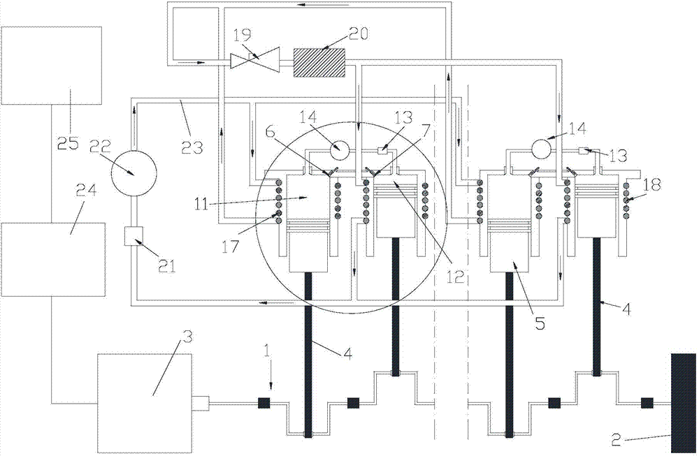
[0037] The medium energy engine device of the present invention is as attached figure 1 , 2 As shown, two cylinder groups are composed of four cylinders with different functions, which are respectively two hot cylinders 11 and two cold cylinders 12 to form an independent closed cycle work system, and each hot cylinder 11 and each cold cylinder Piston 5 is housed in 12, and piston 5 is connected with connecting rod 4; The cylinder group is connected to flywheel 2, generator 3 and connecting rod 4 on crankshaft 1; The cylinder group is provided with first valve 6 on each hot cylinder 11 , each cold cylinder 12 is provided with a second air valve 7, and each first air valve 6 communicates with each second air valve 7 with a conduit; each hot cylinder 11 is provided with a liquid injection port 8, and each cold cylinder 12 A liquid outlet 9 is provided, and a second electromagnetic valve 10, a liquid storage tank 13, a booster pump 14 and a first electromagnetic valve 15 are inst...


PUM


Abstract

The invention relates to a medium energy engine device and an acting mode of the medium energy engine device. The medium energy engine device comprises air cylinder sets, a flywheel, a generator and connecting rods, and the flywheel, the generator and the connecting rods are connected to a crankshaft. Each air cylinder set is formed by two air cylinders with different functions, namely, a hot cylinder and a cold cylinder, a sealed circulating acting system is formed by each hot cylinder and the corresponding cold cylinder, pistons are arranged in the hot cylinders and the cold cylinders, and the pistons are connected with the connecting rods. Booster pumps, first solenoid valves, second solenoid valves, first valves, second valves, a compressor and the generator of the device are connected with a storage battery and a central controller, and an acting pipeline and a heat pump pipe network are filled with different work media and are in independent sealed circulation. After the heat of outer media is absorbed by an evaporator, heat energy is converted into mechanical energy through the reciprocating motion of the pistons in the air cylinder sets. The medium energy engine device and the acting mode of the device have the advantages that breakthroughs are achieved in medium energy utilization, and meanwhile a new field is created for development and utilization of new energy.

Description

technical field [0001] The invention belongs to the technical field of engine devices, in particular to a dual-matter independent closed-circulation piston type medium-energy engine device and its working method. Background technique [0002] There are many existing devices that can do work through a medium. For example, we use geothermal energy and air energy as heat sources to provide energy for our lives. These are inexhaustible and inexhaustible green energies on the earth, and they are also the best choice for the long-term energy needed by human beings. These energies are not only green and environmentally friendly, but also not as non-renewable as mineral energy. The most important thing is that these energies are always around us without transportation or refining. Especially in the era when automobiles are increasingly becoming an indispensable means of transportation for our travel, as the oil resources consumed by automobiles are getting less and less, the exhaus...

Claims


Application Information

Patent Timeline
Patent Type & Authority Applications(China)
IPC IPC(8): F02G1/044
CPCF02G1/044F02G2244/08F05D2210/12F05D2210/14
Inventor 陈峰磊
Owner NINGBO HI TECH ZONE JINSHAN NEW ENERGY SCI & TECH CO LTD
Why Eureka
Try Eureka