Method, system and node for realizing auto protection switching in Optical Burst-Switching Ring

A technology of automatic protection switching and optical burst switching, applied in the direction of data switching network, transmission system, digital transmission system, etc., can solve the problems of waste of resources, inability to use directly, and little significance, so as to ensure the quality of communication and make full use of usability Effect

Active Publication Date: 2015-01-21
ZTE CORP +1
View PDF19 Cites 5 Cited by
  • Summary
  • Abstract
  • Description
  • Claims
  • Application Information

AI Technical Summary

Problems solved by technology

However, in the steering mode protection switching of RPR, the default node can perform optical-to-optical conversion for services, so the switching scheduling is simple, but it cannot be directly used in the OBRing network, especially for centralized control OBRing, the control information of bandwidth allocation is still There must be a path that can traverse all nodes at one time and return to the master node, and the traditional steering mode based on distributed control does not consider this special requirement
In fact, the cut-through mode is also aimed at the node of optical-to-optical conversion. In the case of a fault in the electrical domain, this node can be directly spanned in the optical domain by switching, so as to ensure that the remaining nodes of the network can continue to work. However, in OBRing nodes It supports transparent penetration of services, and only controls the optical-to-optical conversion of the channel, so the cut-through mode is of little sign

Method used


Image

  • Method, system and node for realizing auto protection switching in Optical Burst-Switching Ring
  • Method, system and node for realizing auto protection switching in Optical Burst-Switching Ring
  • Method, system and node for realizing auto protection switching in Optical Burst-Switching Ring

Examples


Embodiment Construction

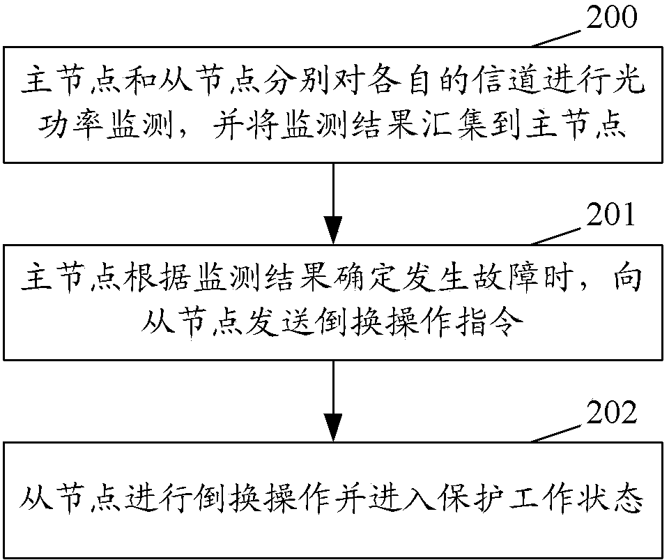
[0073] figure 2 It is a flow chart of the method for realizing automatic protection switching in the optical burst switching ring network of the present invention, as figure 2 shown, including the following steps:

[0074] Step 200: the master node and the slave node respectively monitor the optical power of their respective channels, and collect the monitoring results to the master node.

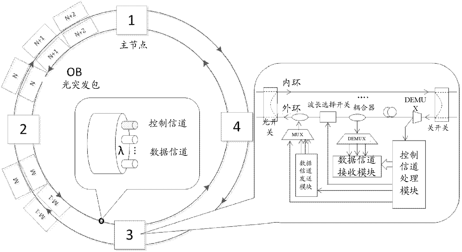
[0075] In this step, the master node and each slave node respectively monitor the optical power status (also called optical path status) of the control channel and the data channel in real time. Among them, the monitoring result of the optical path state monitored by the slave node can be carried in the control frame or the newly added fault report message, and transmitted to the master node through the control channel; the monitoring result of the optical path state on the master node includes its own control channel The monitoring results of real-time monitoring of the optical power s...


PUM


Abstract

A method, system, and node for implementing automatic protection switchover in an optical burst switch ring. The method comprises: a primary node and a secondary node separately performing optical power monitoring on separate channels, and aggregating monitoring results to the primary node; when determining, according to the monitoring results, that a fault occurs, the primary node sending a switchover operation instruction to the secondary node; and the secondary node performing a switchover operation and entering a protection working state. By using the present invention, a protection switchover mechanism is introduced to the optical burst switch ring, processing on the fault is implemented, and communication quality in the optical burst switch ring is ensured. Further, in the method of the present invention, different switchover operation manners are used for a data channel and a control channel, which meets a protection requirement of a centralized-control optical burst switch ring for a control channel loop, ensures that the control channel can still work in a primary-secondary ring working mode, considers utilization of a transceiver on a data channel, and brings availability of a transceiver on each node into full play.

Description

technical field [0001] The present invention relates to network protection technology, in particular to a method, system and node for realizing automatic protection switching in a centrally controlled Optical Burst-switching Ring (OBRing, Optical Burst-switching Ring). Background technique [0002] The continuous development of the Internet, especially with the increase in the number of users, the continuous increase in bandwidth demand, and the general promotion of cloud service models, makes it increasingly difficult for the traditional metropolitan aggregation network to cope with the high flexibility and bandwidth provided by services. High reliability and low energy consumption requirements. Under the background of such demand, Optical Burst-switching Ring (OBRing, Optical Burst-switching Ring), as an all-optical networking technology capable of providing sub-wavelength switching granularity, has been extensively researched and paid attention to. Such as figure 1 As s...

Claims


Application Information

Patent Timeline
IPC IPC(8): H04B10/032H04B10/079
CPCH04B10/032H04B10/07955H04B10/275H04Q11/0066H04Q2011/0081H04Q2011/0092H04L12/437H04L41/0668
Inventor 郭宏翔张东旭陈雪伍剑安高峰
Owner ZTE CORP
Why Eureka
Try Eureka