LED constant current source output detection control circuit and control method thereof

A technology for output detection and control circuits, applied in energy-saving control technology, lamp circuit layout, light source, etc., can solve the problem of high cost, abnormal output signal cannot be reliably and effectively judged, and demagnetization time detection cannot be obtained directly, effectively and timely Signal and other issues

Active Publication Date: 2015-01-21
QX MICRO DEVICES
View PDF4 Cites 10 Cited by
  • Summary
  • Abstract
  • Description
  • Claims
  • Application Information

AI Technical Summary

Problems solved by technology

[0004] The disadvantage of the traditional low-end switching circuit architecture control system is that the chip detects the inductance demagnetization time in the system indirectly through the auxiliary winding or approximates it through the principle of capacitive coupling, and cannot directly and effectively obtain the demagnetization time detection si

Method used


Image

  • LED constant current source output detection control circuit and control method thereof
  • LED constant current source output detection control circuit and control method thereof
  • LED constant current source output detection control circuit and control method thereof

Examples


Embodiment 1

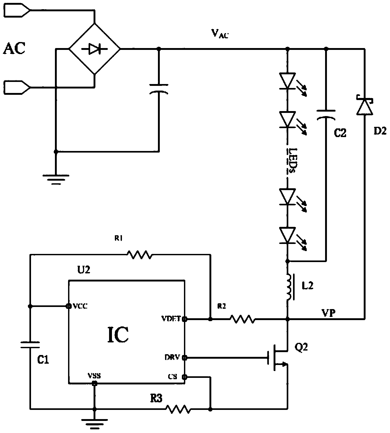
[0040] combine figure 1 As shown, it is the first specific embodiment of the LED constant current source output detection control circuit disclosed by the present invention. In this embodiment, the LED constant current source output detection control circuit includes a rectification module electrically connected to an AC input power supply, and the rectification module An output load and an inductor L2 are connected to the output terminal, specifically in this embodiment, combined with figure 1 It can be seen that the output load is a plurality of light-emitting LEDs connected in series, and the plurality of light-emitting LEDs form an LED light string, and a capacitor C2 is connected in parallel to the LED light string.

[0041] In addition, the LED constant current source output detection control circuit also includes a chip U2, a power switch tube Q2, a resistor R1 and a resistor R2; figure 1 , we describe its connection structure in detail. One end of the inductor L2 is c...

Embodiment 2

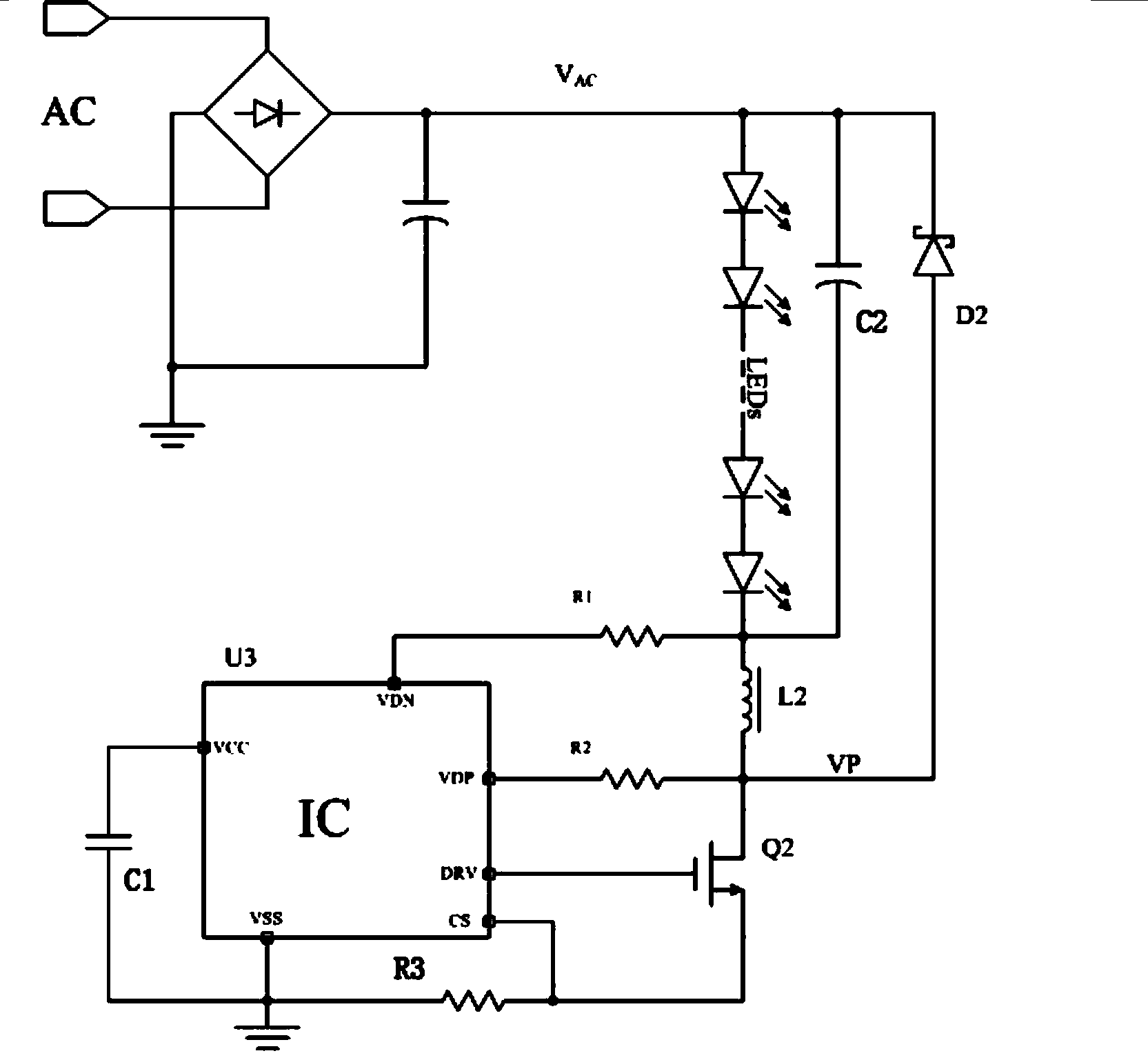
[0058] combine image 3 As shown, it is the second specific embodiment of the present invention, combining image 3 We describe the structure in this embodiment in detail.

[0059] An LED constant current source output detection control circuit disclosed by the present invention includes a rectification module electrically connected to an AC input power supply, an output load and an inductor L2 are connected to the output end of the rectification module, and the output load is a plurality of light-emitting LEDs connected in series, A capacitor C2 is connected in parallel with the output load.

[0060] It also includes a chip U3, a power switch tube Q2, a resistor R1 and a resistor R2. One end of the inductor L2 is connected to the output load, and the other end of the inductor L2 is connected to the drain of the power switch tube Q2, and the connected line has a connection node, the chip U3 has pins VCC, pin VDP, pin VDN and pin DRV, the gate of the power switch tube Q2 is c...

Embodiment 3

[0067] combine Figure 4 As shown, it is the third specific embodiment of the present invention, combining Figure 4 We describe the structure in this embodiment in detail.

[0068] Referring to the first embodiment figure 2 and in this example Figure 4 It can be seen that the connection structures of the resistor R1, the resistor R2, the chip U2 (U4), and the power switch tube Q2 (Q4) are the same in both embodiments. This embodiment is an isolated flyback cross-current control system. Of course, this embodiment The invention can also adopt the output detection control of other LED constant current control systems.

[0069]Specifically, the system also includes a transformer T, the transformer T has a primary winding and a secondary winding, wherein the primary winding of the transformer T is equivalent to the inductance L2 in Embodiment 1; one end of the secondary winding of the transformer T is connected to The positive end of the freewheeling diode D2, the negative e...


PUM


Abstract

The invention discloses an LED constant current source output detection control circuit and a control method thereof, and relates to the technical field of LED driving power sources. The LED constant current source output detection control circuit comprises an output load, an inductor L2, a chip U2, a power switch tube Q2, a resistor R1 and a resistor R2. One end of the inductor L2 is connected to the drain of the power switch tube Q2, and the connection line is provided with a connection node. The chip U2 is provided with a pin VCC, a pin VDET and a pin DRV. The grid of the power switch tube Q2 is connected to the pin DRV. One end of the resistor R2 is connected to the pin VDET, and the other end of the resistor R2 is connected to the connection node. One end of the resistor R1 is connected to the pin VCC, and the other end of the resistor R1 is connected to the common end of the pin VDET and the resistor R2. The LED constant current source output detection control circuit and the control method thereof have the advantages that the demagnetization time of the inductor can be instantly obtained, output voltage and input voltage are detected, and the constant current effect and reliability of a system are improved.

Description

technical field [0001] The invention relates to the technical field of LED driving power supply; in particular, it relates to an output detection control circuit of an LED constant current source and a control method thereof. Background technique [0002] With the popularization and application of LED driving power, the development of various LED driving chips is also showing a vigorous upward trend. The development of LED drive has experienced constant voltage drive mode, linear constant current drive mode, switching power supply constant current drive mode, and quasi-linear constant current drive mode. Among them, the switching power supply constant current drive mode is the most popular in the market. It has good constant current characteristics, a variety of switching architectures, and good reliability. The low-end switch structure is popularized and used by designers and customers because of its stability and good adjustability. [0003] In the traditional low-end sw...

Claims


Application Information

Patent Timeline
IPC IPC(8): H05B37/02
CPCY02B20/40
Inventor 黄朝刚李剑吴玉强
Owner QX MICRO DEVICES
Why Eureka
Try Eureka