Digital controlled lathe for processing engine crank shaft connecting rod

A technology of crankshaft connecting rods and CNC lathes, applied in the field of CNC lathes, which can solve the problem that the shape tolerance and axial distance of a single connecting rod cannot be guaranteed, restrict the processing quality and production efficiency of crankshaft connecting rods, and the consistency gap between multiple connecting rods, etc. problems, to avoid quality accidents and personal injuries, shorten processing time, and reduce labor intensity

Inactive Publication Date: 2015-01-28
山西东鑫衡隆机械制造股份有限公司
View PDF7 Cites 5 Cited by
  • Summary
  • Abstract
  • Description
  • Claims
  • Application Information

AI Technical Summary

Problems solved by technology

Traditional processing lathes are controlled by hydraulic systems, and the axial distance of each connecting rod is guaranteed by fixed length. It is necessary to manually replace and process different connecting rods, which is not only inefficient, time-consuming and laborious, but also the shape and position tolerance of a single connecting rod and the axis The axial distance cannot be guaranteed, there is a large gap in the consistency of multiple connecting rods, and the hydraulic system is greatly affected by the ambient temperature, which has long been a bottleneck problem that has restricted the processing quality and production efficiency of crankshaft connecting rods.

Method used


Image

  • Digital controlled lathe for processing engine crank shaft connecting rod
  • Digital controlled lathe for processing engine crank shaft connecting rod
  • Digital controlled lathe for processing engine crank shaft connecting rod

Examples


Embodiment Construction

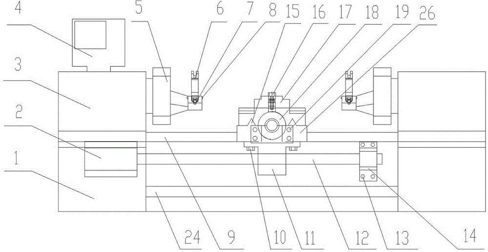
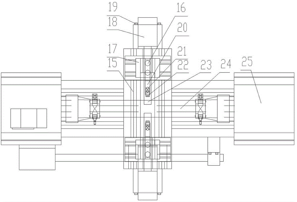
[0015] A numerically controlled lathe for processing engine crankshaft connecting rods, mainly comprising a base 1, a front rotating body 3, a rear rotating body 25, a first servo motor 2, a first lead screw 12, a turning bed surface guide rail 9, and a second servo motor 18 and the second lead screw 23, such as figure 1 , figure 2 , image 3 shown. The base 1 is provided with a front rotating body 3 , a rear rotating body 25 , a turning bed surface guide rail 9 and a first servo motor 2 . The first servo motor 2 is fixed on the lower left side of the turning bed guide rail 9, and the front rotating body 3 and the rear rotating body 25 are respectively installed on the left and right sides near the end of the turning bed guiding rail 9, and the front part rotates Body 3 is connected with rear rotating body 25 through transmission shaft 24 . The turning bed surface guide rail 9 is provided with a turning bed surface 26 that can move left and right along the turning bed sur...


PUM


Abstract

The invention relates to a digital controlled lathe for processing an engine crank shaft connecting rod. The lathe comprises a lathe base, a four-shaft linkage system controller, a first servo motor, a front rotating machine body, a turntable, a turning machine surface guide rail, a turning machine surface guide sleeve, a first lead screw, a lead screw fixing element, a cutter frame guide rail, a cutter fixing seat, second servo motors, a cutter handle, turning cutters, a second lead screw, a transmission shaft, a back following machine body and a turning machine surface. The servo motors are controlled to rotate by the four-shaft linkage system controller, so the turning machine surface is indirectly driven to leftwards and rightwards move, the axial processing dimension of the crank shaft connecting rod is realized, the two front and back second servo motors are controlled to rotate so that the front and back turning cutters are indirectly driven to forwards and backwards move, and the radial processing dimension of the crank shaft connecting rod is realized. The digital controlled lathe has the advantages that a digital controlled operation system is adopted for replacing an original hydraulic system, the operation is simple and convenient, the work efficiency is high, the processing dimension consistency is improved, and the equipment fault repair rate and the processing cost are reduced.

Description

[0001] technical field [0002] The invention relates to mechanical processing equipment, in particular to a numerically controlled lathe for processing engine crankshaft connecting rods. Background technique [0003] The engine crankshaft is an important part of the engine next to the cylinder block. Its processing quality directly affects the overall performance of the engine, and the connecting rod journal is an important part of the crankshaft. Therefore, the processing quality of the connecting rod journal directly affects the performance of the engine. . Traditional processing lathes are controlled by hydraulic systems, and the axial distance of each connecting rod is guaranteed by fixed length. It is necessary to manually replace and process different connecting rods, which is not only inefficient, time-consuming and laborious, but also the shape and position tolerance of a single connecting rod and the axis The axial distance cannot be guaranteed, the consistency of...

Claims


Application Information

Patent Timeline
Patent Type & Authority Applications(China)
IPC IPC(8): B23B5/00B23B9/10
CPCB23B5/08B23B9/005B23B9/08B23Q5/36B23Q5/40B23Q2705/102
Inventor 常显峰禇京生张强强杨超王刚刚王海龙
Owner 山西东鑫衡隆机械制造股份有限公司
Why Eureka
Try Eureka