Machine head structure of wall surface grinding machine
A grinding machine and machine head technology, which is applied to the parts of grinding machine tools, machine tools suitable for grinding workpiece planes, grinding machines, etc., can solve the problem that the wall cannot be easily observed, the grinding effect is not satisfactory, and it is difficult to maintain Balance and other issues to achieve the effect of light weight, easy maintenance and long service life
- Summary
- Abstract
- Description
- Claims
- Application Information
AI Technical Summary
Problems solved by technology
Method used
Image
Examples
Embodiment 1
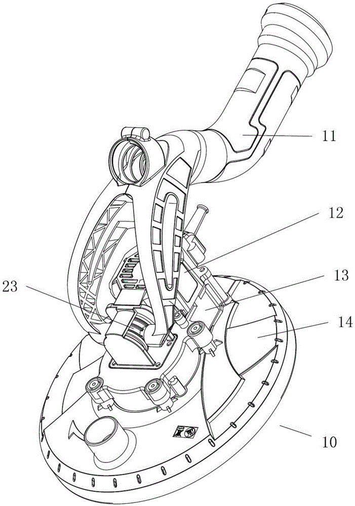
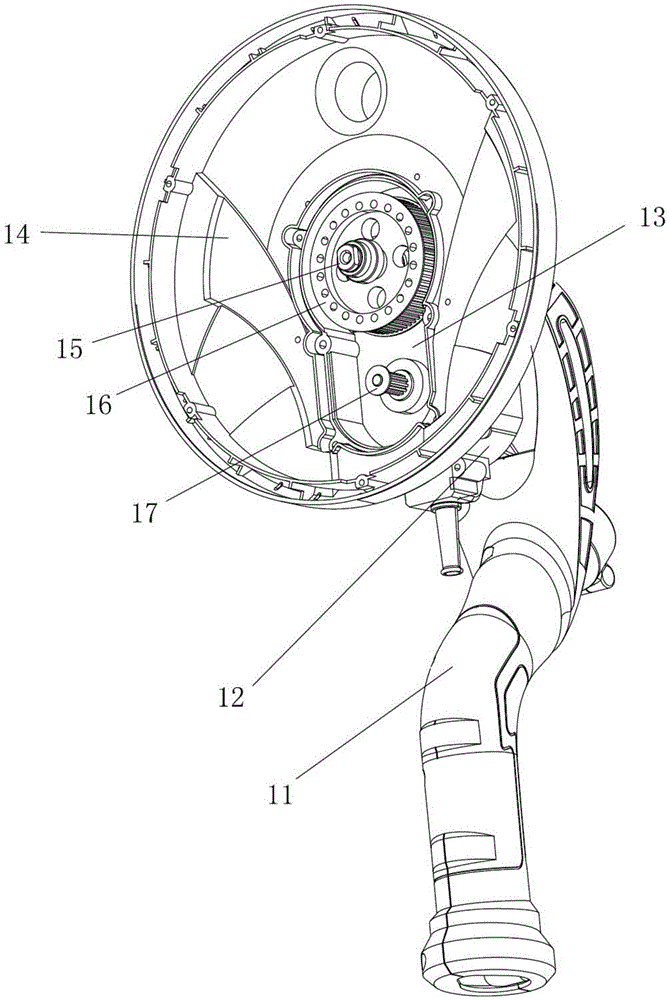
[0047] Example 1, such as Figure 1-2As shown, the head structure of the wall grinder includes a cover 14, a transmission chamber 13 arranged on the cover 14, and a drive motor, the drive motor is a brushless DC motor 12, and the brushless DC motor 12 is installed on the transmission On the chamber 13, a deceleration transmission mechanism is provided in the transmission chamber 13, and the motor shaft of the brushless DC motor 14 stretches into the transmission chamber and drives the deceleration transmission mechanism, and the output shaft 15 of the transmission mechanism drives the grinding disc assembly (not shown). figure 2 In the figure, the bottom cover of the transmission chamber is drawn, and the peripheral side of the bottom cover is connected with the upper cover of the transmission chamber by bolts.
[0048] Preferably, the reduction transmission mechanism includes a first synchronous pulley 17 and a second synchronous pulley 16, which are connected by a synchrono...
Embodiment 2
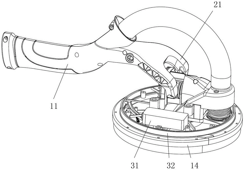
[0050] Example 2, such as Figure 3-6 As shown, this embodiment is improved on the basis of Embodiment 1, wherein a light strip assembly is provided on the protective cover 14 of the machine head, and the light strip assembly includes an LED light strip 33 and a lampshade 32; the protective cover The LED light strip 33 is installed on the peripheral side of 14, the lampshade 32 covers the LED light strip 33 and prevents dust from touching the LED light strip 33, the light emitted by the LED light strip 33 passes through the lampshade 32 and shines on the protective cover 14 side wall. The LED lamp of the present invention is installed on the protective cover. Compared with the design of the existing lighting lamp (installed on the lower side of the middle part of the operating handle), the light emitted by the LED lamp reaches people's eyes after being reflected by the wall. The position of the LED lamp and The position of the eyes is more in line with the optical design, mak...
Embodiment 3
[0059] Example 3, such as Figure 7-11 As shown, this embodiment is improved on the basis of Embodiment 1, wherein the left and right pin shafts of the machine head 10 are connected to the front fork 21 of the front handle 11 (although only the front fork is shown in the figure 21 and the right pin 22, naturally, the cooperation of the front fork 21 and the left pin adopts the same structure), in the left and right pins, at least one of the pins is equipped with a torsion spring, the present embodiment Among them, the torsion spring is only arranged on the right pin shaft 22, the base 25 of the torsion spring is sleeved on the right pin shaft 22, and the end 201 inside the base is connected with the right pin shaft 22. The outer end of the base 25 extends to form a hook 26, which can hook the front fork 21 and turn the machine head 14 at a certain angle (in this embodiment, when the operating handle is lifted vertically, the torsion spring makes the machine The grinding disc ...
PUM
 Abstract
Description
Claims
Application Information
 - R&D
- Intellectual Property
- Life Sciences
- Materials
- Tech Scout
- Unparalleled Data Quality
- Higher Quality Content
- 60% Fewer Hallucinations
Browse by: Latest US Patents, China's latest patents, Technical Efficacy Thesaurus, Application Domain, Technology Topic, Popular Technical Reports.
© 2025 PatSnap. All rights reserved.Legal|Privacy policy|Modern Slavery Act Transparency Statement|Sitemap|About US| Contact US: help@patsnap.com


