Low-strain measurement device for fixed pile foundation with grasping pile

A fixed, positioning device technology, used in infrastructure engineering, infrastructure testing, analysis of solids using sonic/ultrasonic/infrasonic waves, etc. Achieving good fixing effect and saving labor

Active Publication Date: 2016-01-20
重庆建设工程质量监督检测中心有限公司
View PDF5 Cites 0 Cited by
  • Summary
  • Abstract
  • Description
  • Claims
  • Application Information

AI Technical Summary

Problems solved by technology

However, the existing low-strain dynamic measuring instrument is not suitable for use in deep water. On the one hand, when using the dynamic measuring instrument for detection, two people are generally required to cooperate. One person presses the probe on the pile head, and the other hand The hand hammer or power hammer hits the top of the pile to generate a stress wave, and another person initially judges whether the curve is qualified through the display of the pile detector connected to the probe, and records the corresponding pile number, and then uses special software to further analyze the data; On the other hand, in the deep water high pressure environment, the use of artificial diving for low-strain operations is not only high in labor costs, complicated and difficult to operate, but also the probe of the dynamic tester will seep into the water under the high pressure of deep water, resulting in a decrease in the sensitivity of the probe, and the low-strain curve knocked out Distorted messy, poor results
Expensive labor costs, high difficulty of detection and poor detection effect severely limit the application of low-strain dynamic detectors in marine and river-sea pile foundation detection

Method used


Image

  • Low-strain measurement device for fixed pile foundation with grasping pile
  • Low-strain measurement device for fixed pile foundation with grasping pile
  • Low-strain measurement device for fixed pile foundation with grasping pile

Examples


Embodiment Construction

[0024] Embodiments of the present invention will be described in further detail below in conjunction with the accompanying drawings.

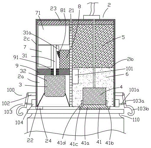
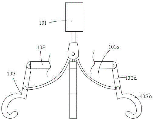
[0025] Figure 1 to Figure 7 Shown is the structural representation of the present invention.

[0026] The reference signs are: data processor 1, controller 11, stress wave generating and receiving device 2, left cavity 2a, right cavity 2b, housing 2c, waterproof interlayer 21, flexible water-proof membrane 22, glue layer 23. Balance foot 24, hammer 3, hammer handle 31, clamping block 31a, hammer head 32, stress wave receiving probe 4, pressure isolation block 41, pressure isolation hard layer 41a, adhesive glue layer 41b, sealing shoulder 41c, sealing ring 41d, counterweight 5, damping layer 6, driving motor 7, cylinder 71, gear block 8, locking protrusion 81, sealing flange 9, sealing floating ring 91, positioning device 100, push-pull motor 101 , a push-pull rope 101a, a protruding rod 102, a pile grabber 103, a grabbing rod 103a, a hook 1...


PUM


Abstract

The invention discloses a pile grabbing fixed type dynamic testing device for low strain of a pile foundation. A driving hammer and a stress wave receiving probe are integrated in a stress wave generation receiving device, the driving hammer falls and retracts automatically, the stress wave generation receiving device is fixed at the top of the pile foundation through a balancing weight and a fixing device, and an adhesive bonding colloid layer is arranged at the lower end of the stress wave receiving probe to realize the better medium connection between the stress wave receiving probe and the pile at the lower part. The stress wave generation receiving device is provided with a locating device, and the locating device comprises a push-pull motor arranged in the stress wave generation receiving device, a plurality of protruded rods at the outer lateral surface of the shell body and the same number of pile grabbers. By means of the pile grabbing fixed type dynamic testing device for the low strain of the pile foundation, the low strain test for the pile can be finished by one person, and moreover, the person only needs to debug a data processor on a water platform, and the test cost is greatly saved. The pile grabbing fixed type dynamic testing device for the low strain of the pile foundation can be used in deep water under high pressure, and the pile grabbing fixed type dynamic testing device for the low strain of the pile foundation combines the driving hammer with a detection probe, saves manpower and has good fixing effect.

Description

technical field [0001] The invention relates to the technical field of pile foundation detection, in particular to a pile foundation detection device in a high water pressure environment, in particular to a pile-grabbing fixed-type pile foundation low-strain detection device. Background technique [0002] Large-diameter cast-in-situ piles are widely used because of their high bearing capacity and low construction noise. They are usually excavated manually or drilled into holes and poured into piles underground or underwater. The quality is affected by the construction process, especially the concrete pouring. It is difficult to control due to the influence of various factors such as working procedures, so the quality problems of pile foundations generally exist, such as too thick sediment, uneven pile body (local mud, segregation, honeycomb, etc.). Therefore, before proceeding to the next process, the quality and integrity of the concrete body of the pile must be inspected a...

Claims


Application Information

Patent Timeline
Patent Type & Authority Patents(China)
IPC IPC(8): G01N29/12E02D33/00
CPCE02D27/12E02D33/00
Inventor 张海瑛米荣彦
Owner 重庆建设工程质量监督检测中心有限公司
Why Eureka
Try Eureka