Gas-liquid pressure cylinder

A gas-hydraulic pressurized cylinder and hydraulic cylinder technology, which is applied in the field of rail vehicle braking systems, can solve the problems of complex structure, space occupation of pressurized cylinders, and high maintenance and repair costs, and achieve simple and compact structure, reduced labor intensity, and maintenance costs. low effect

Inactive Publication Date: 2015-01-28
ZHUZHOU ELECTRIC LOCOMOTIVE CO
View PDF7 Cites 15 Cited by
  • Summary
  • Abstract
  • Description
  • Claims
  • Application Information

AI Technical Summary

Problems solved by technology

Each car of the existing maglev train has 16 hydraulic branches, and each branch has a gas-liquid booster cylinder and an oil supply port. Each gas-liquid booster cylinder contains an oil storage chamber inside, occupying an increased Cylinder space, complex structure, heavy weight; when replenishing oil, the exhaust plug on each oil storage chamber must be removed, and the oil discharge bolt and oil discharge hose must be installed. After oil replenishment, the oil discharge bolt and oil discharge hose must be removed The oil discharge hose and the installation of the exhaust screw plug, the operation process is cumbersome and the maintenance cost is high
[0004] In addition, the existing gas-liquid booster cylinder indirectly feeds back the hydraulic pressure status by monitoring the working air pressure, and feeds back oil supply or abnormal work information through the pressure switch, which inevitably differs from the actual hydraulic pressure, and the inaccuracy of hydraulic pressure monitoring affects The working conditions of the hydraulic actuators make it difficult to ensure the safe operation of the train

Method used


Image

  • Gas-liquid pressure cylinder

Examples


Embodiment Construction

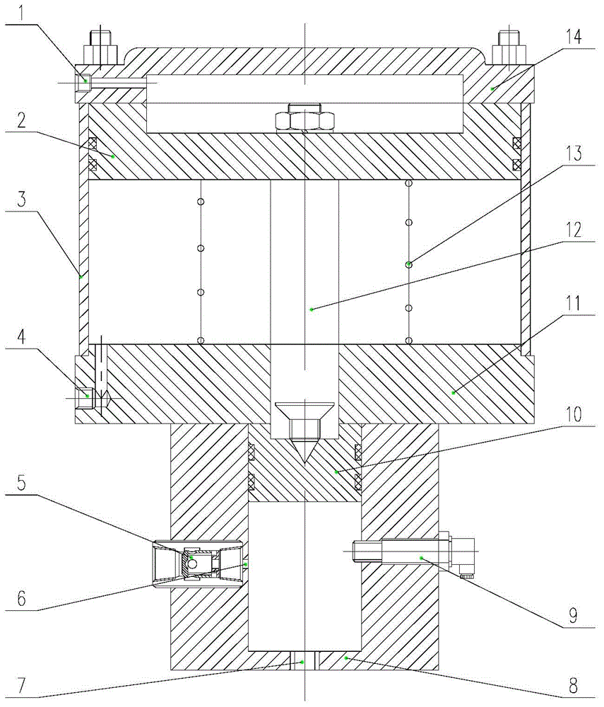
[0028] The invention discloses a gas-liquid pressurized cylinder, which is used in conjunction with the brake system of a medium-low speed magnetic levitation train to realize automatic oil replenishment, reduce labor intensity of workers, and is convenient for maintenance and reliable in operation.

[0029] The following will clearly and completely describe the technical solutions in the embodiments of the present invention with reference to the accompanying drawings in the embodiments of the present invention. Obviously, the described embodiments are only some, not all, embodiments of the present invention. Based on the embodiments of the present invention, all other embodiments obtained by persons of ordinary skill in the art without making creative efforts belong to the protection scope of the present invention.

[0030] see figure 1 , figure 1 Schematic diagram of the structure of the gas-liquid booster cylinder provided by the embodiment of the present invention.

[00...


PUM


Abstract

The invention discloses a gas-liquid pressure cylinder. The gas-liquid pressure cylinder is not provided with an oil storage cavity and is simple and compact in structure, convenient to maintain, high in efficiency, and saves energy. An oil inlet is formed in a liquid cylinder body and communicated with an oil storage tank of a braking system through a one-way valve. When the pressure cylinder does not have pressure air, the one-way valve is opened, and the oil storage tank is communicated with the pressure cylinder. After the pressure cylinder is filled with compressed air, due to the pressure action, the one-way valve is closed, and the passage between the oil storage tank and the pressure cylinder is cut off. The gas-liquid pressure cylinder can realize automatic oil supplement, lowers the labor intensity, and is low in maintenance cost. As a hydraulic sensor is arranged in the liquid cylinder body, the gas-liquid pressure cylinder has a real-time pressure monitoring function, can quickly and accurately feedback and display hydraulic pressure information, can carry out an early-warning prompt for abnormal pressure, and is convenient for a hydraulic system to maintain and find faults. The gas-liquid pressure cylinder is convenient to add oil and can monitor and feedback the hydraulic pressure in real time, all the operations are automatically completed during working, and the practicality is strong. The gas-liquid pressure cylinder is used together with low-speed and middle-speed maglev train braking systems, lowers the labor intensity of workers, and is convenient to maintain and reliable in work.

Description

technical field [0001] The invention relates to the technical field of rail vehicle braking systems, in particular to a gas-hydraulic booster cylinder. Background technique [0002] The gas-liquid booster cylinder is a fast gas-liquid booster device with high efficiency, energy saving, low noise and zero pollution. [0003] At present, domestic low- and medium-speed maglev trains generally use air-to-hydraulic brake systems, and both brake calipers and support wheels need to work in a hydraulic state. Each car of the existing maglev train has 16 hydraulic branches, and each branch has a gas-liquid booster cylinder and an oil supply port. Each gas-liquid booster cylinder contains an oil storage chamber inside, occupying an Cylinder space, complex structure, heavy weight; when replenishing oil, the exhaust screw plug on each oil storage chamber must be removed, and the oil discharge bolt and oil discharge hose must be installed, and the oil discharge bolt and oil discharge ho...

Claims


Application Information

Patent Timeline
Patent Type & Authority Applications(China)
IPC IPC(8): F15B15/14F15B15/20F15B3/00
CPCF15B15/14F15B3/00F15B15/1423F15B15/202F15B19/005F15B2211/87
Inventor 宋丽伟毛莉高锋佟来生罗华军王明华
Owner ZHUZHOU ELECTRIC LOCOMOTIVE CO
Why Eureka
Try Eureka