TOF depth camera three-dimensional coordinate calibration device and method based on virtual multi-cube standard target

A technology of depth camera and three-dimensional coordinates, which is applied in the direction of measuring devices, optical devices, instruments, etc., can solve the problem of high complexity of target recognition and feature extraction, large number of target features, and affecting the accuracy and repeatability of TOF depth camera calibration results And other issues

Active Publication Date: 2015-01-28
ACAD OF OPTO ELECTRONICS CHINESE ACAD OF SCI
View PDF8 Cites 22 Cited by
  • Summary
  • Abstract
  • Description
  • Claims
  • Application Information

AI Technical Summary

Problems solved by technology

[0006] (2) The TOF depth camera calibration method based on the complex feature three-dimensional markers, such as using three-dimensional objects with different depth features such as cubes or multi-layer steps as the standard measurement object for the TOF depth camera calibration method (1.Tsai, R.A versatile camera calibration technique for high-accuracy 3D machine vision metrology using off-the-shelf TV cameras and lenses.IEEE Journal of Robotics and Automation.1987.RA-3(4):323-344; 2. Xu De, Tan Min, Li Yuan. Robot Vision Measurement and Control. National Defense Industry Press. 2011.05; 3. Filiberto Chiabrando, Roberto Chiabrando, Dario Piatti, Fulvio Rinaudo. Sensors for 3D Imaging: Metric Evaluation and Calibration of a CCD / CMOS Time-of-Flight Camera .Sensors.2009(9):10080-10096; 4.Stuart Robson,J.-Angelo Beraldin,Andrew Brownhill and Lindsay MacDonald.Artefacts for Optical Surface Measurement.Proc.of SPIE Vol.8085,Videometrics,Range Imaging,and Applications XI, 80850C.May23, 2011.Munich, Germany; 5. Patent 201210352365.1 "Three-dimensional measurement method based on computer vision cube calibration"), although these methods can directly collect different depth information at different positions on the surface of complex features, Then, the measurement error of the TOF depth camera is calculated and compensated. However, due to the need to extract and identify the complex features acquired at the same time, the calculation is large and the extraction error will be accumulated in the final calibration result. The three-dimensional coordinate calibration of the TOF depth camera Accuracy and three-dimensional measurement accuracy are also difficult to further improve
[0007] From the above analysis, it can be seen that in practical applications, the currently widely used calibration methods of TOF depth cameras have the following shortcomings: the number of target features that appear in the field of view in a single acquisition of TOF depth cameras is large, making The data processing process is long, and the complexity of target recognition and feature extraction is high, which directly leads to the accumulation of measurement errors in target recognition and feature extraction into the 3D coordinate calibration results of the TOF 3D camera, which greatly affects the accuracy of the TOF depth camera calibration results And repeatability, thus limiting the application range of TOF depth cameras, this is the deficiency of the existing calibration scheme itself, and it is also an important problem that the current TOF depth cameras cannot solve in practical applications

Method used


Image

  • TOF depth camera three-dimensional coordinate calibration device and method based on virtual multi-cube standard target
  • TOF depth camera three-dimensional coordinate calibration device and method based on virtual multi-cube standard target
  • TOF depth camera three-dimensional coordinate calibration device and method based on virtual multi-cube standard target

Examples


Embodiment 1

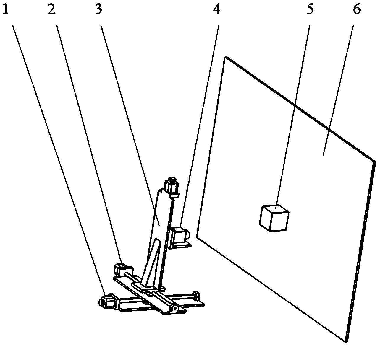
[0045] (1) Taking the TOF depth camera 4 at a distance of 0.5m, the combination of the X-direction moving translation platform 2 and the Y-direction moving translation platform 3 to carry out 3×3 movement in the XY plane as an example, describe in detail the calibration device introduced in the present invention and Methods as below:

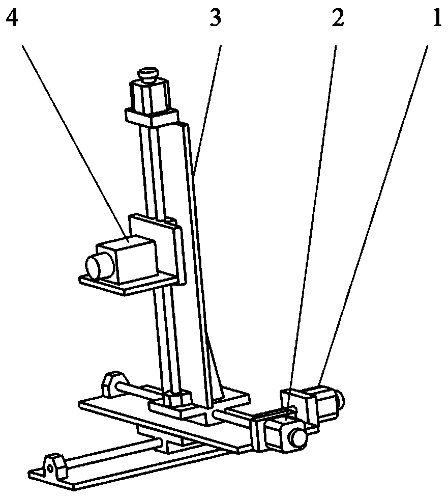
[0046] Such as figure 1 As shown, first determine the TOF depth camera 4 coordinate system OXYZ, the three translation axes of the three-dimensional translation stage are defined as the three directions of X, Y, and Z, the coordinate origin O is positioned as the lens center of the TOF depth camera 4, and the three-dimensional motion translation stage is installed The bottom surface is defined as the XZ plane, which is parallel to the bottom surface of the TOF depth camera 4; the Z direction is the optical axis direction of the TOF depth camera 4, which is parallel to the movement direction of the translation axis of the Z-direction translation ...

Embodiment 2

[0058] Such as figure 1 As shown, the cube target 5 is in the shape of a cuboid whose length, width and height are not completely equal. The other components and working principles of this embodiment are the same as those of Embodiment 1.


PUM


Abstract

The invention relates to a TOF depth camera three-dimensional coordinate calibration device and method based on a virtual multi-cube standard target. The device comprises a three-dimensional motion horizontally-moving platform, a TOF depth camera, a cubical target and a background board. The calibration method includes the steps that three orthometric one-dimensional motion horizontally-moving platforms move repeatedly in the three-dimensional direction, the virtual multi-cube standard target of a complex shape and with multiple feature points is formed, the space position and the three-dimensional measured coordinates of a target angular point can be accurately obtained, and high-precision three-dimensional coordinate calibration of the TOF depth camera is achieved. By means of the TOF depth camera three-dimensional coordinate calibration device and method, target angular point feature recognition difficulty of the TOF depth camera and measurement errors each time are greatly reduced, three-dimensional measurement precision of the TOF depth camera is improved, the angular point position and the number of feature points of the virtual multi-cube standard target can be set flexibly, and full-process high-precision automatic calibration is achieved easily.

Description

technical field [0001] The invention belongs to the technical field of optical metrology and calibration, and in particular relates to a calibration device and method for a non-scanning laser three-dimensional TOF (Time-of-Flight) depth camera based on a virtual multi-cube standard target. Background technique [0002] With the continuous improvement and improvement of optical measurement and computer vision technology, the development of advanced manufacturing technology and the diversification of product requirements, the demand for measurement of three-dimensional shape information on the surface of complex objects continues to increase, which promotes the continuous development of optical three-dimensional measurement technology and has become One of the main fields and directions of optical metrology and information optics. [0003] As a new generation of optical three-dimensional measurement technology, the TOF depth camera can obtain the grayscale information of space...

Claims


Application Information

Patent Timeline
Patent Type & Authority Applications(China)
IPC IPC(8): G01B11/24G01C25/00
Inventor 敖磊刘永奇董鑫熊胜军
Owner ACAD OF OPTO ELECTRONICS CHINESE ACAD OF SCI
Why Eureka
Try Eureka