A device and method for three-dimensional coordinate calibration of tof depth cameras based on virtual multi-sphere center positioning

A technology of depth camera and calibration method, which is applied in measurement devices, testing of machine/structural components, instruments, etc., can solve problems affecting the accuracy and repeatability of TOF depth camera calibration results, high complexity of target recognition and feature extraction, and limitations. TOF depth camera application range and other issues, to achieve the effect of improving 3D coordinate calibration accuracy, reducing difficulty and error, and reducing error

Active Publication Date: 2017-09-12
ACAD OF OPTO ELECTRONICS CHINESE ACAD OF SCI
View PDF6 Cites 0 Cited by
  • Summary
  • Abstract
  • Description
  • Claims
  • Application Information

AI Technical Summary

Problems solved by technology

[0005] (2) A three-dimensional coordinate calibration method based on complex feature three-dimensional markers, such as using three-dimensional objects with different depth characteristics such as cubes or multi-layer steps as standard measurement objects for TOF depth camera calibration method (1.Tsai, R.Aversatile camera calibration technique for high-accuracy 3D machine visionmetrology using off-the-shelf TV cameras and lenses.IEEE Journal of Robotics and Automation.1987.RA-3(4):323-344; 2. Xu De, Tan Min, Li Yuan . Robot Vision Measurement and Control. National Defense Industry Press. 2011.05; 3. Filiberto Chiabrando, Roberto Chiabrando, Dario Piatti, Fulvio Rinaudo. Sensors for 3D Imaging: Metric Evaluation and Calibration of aCCD / CMOS Time-of-Flight Camera. Sensors. 2009(9):10080-10096; 4. Stuart Robson, J.-Angelo Beraldin, Andrew Brownhill and Lindsay MacDonald. Artefacts for Optical Surface Measurement. Proc. of SPIE Vol.8085, Videometrics, Range Imaging, and Applications XI, 80850C. May 23, 2011.Munich, Germany; 5. Patent 201210352365.1 "3D measurement method based on computer vision cube calibration"), compared with the 3D coordinate calibration method based on planar markers, although this type of method can directly acquire complex feature surfaces Different depth information at different positions on the model, and then calculated to obtain the measurement error of the TOF depth camera for compensation. However, due to the need to extract and identify the complex features acquired at the same time, at the same time, after the target deviates from the center of the field of view, the center of the field of view The acquired target has multiple surfaces, the amount of data calculation is large, and the extraction and recognition errors will be accumulated in the final calibration result. It is difficult to further improve the three-dimensional coordinate calibration accuracy and measurement accuracy of the TOF depth camera.
[0006] From the above analysis, it can be seen that in practical applications, the currently widely used 3D coordinate calibration methods for TOF depth cameras have the following deficiencies: the number of target features that appear in the field of view in a single acquisition of TOF depth cameras, especially It is a three-dimensional coordinate calibration method based on complex feature three-dimensional markers. When the target deviates from the center of the field of view, the three-dimensional target acquired in the field of view presents multi-surface features (for example, after the cuboid target deviates from the center of the field of view, redundant surface topography will be detected. ), and the multi-surface features change with different measurement angles, which makes the data processing process long, and the target recognition and feature extraction complexity is high, which directly leads to the accumulation of measurement errors in target recognition and feature extraction into the calibration results , which greatly affects the accuracy and repeatability of the TOF depth camera calibration results, thereby limiting the application range of the TOF depth camera. important question

Method used


Image

  • A device and method for three-dimensional coordinate calibration of tof depth cameras based on virtual multi-sphere center positioning
  • A device and method for three-dimensional coordinate calibration of tof depth cameras based on virtual multi-sphere center positioning
  • A device and method for three-dimensional coordinate calibration of tof depth cameras based on virtual multi-sphere center positioning

Examples


Embodiment 1

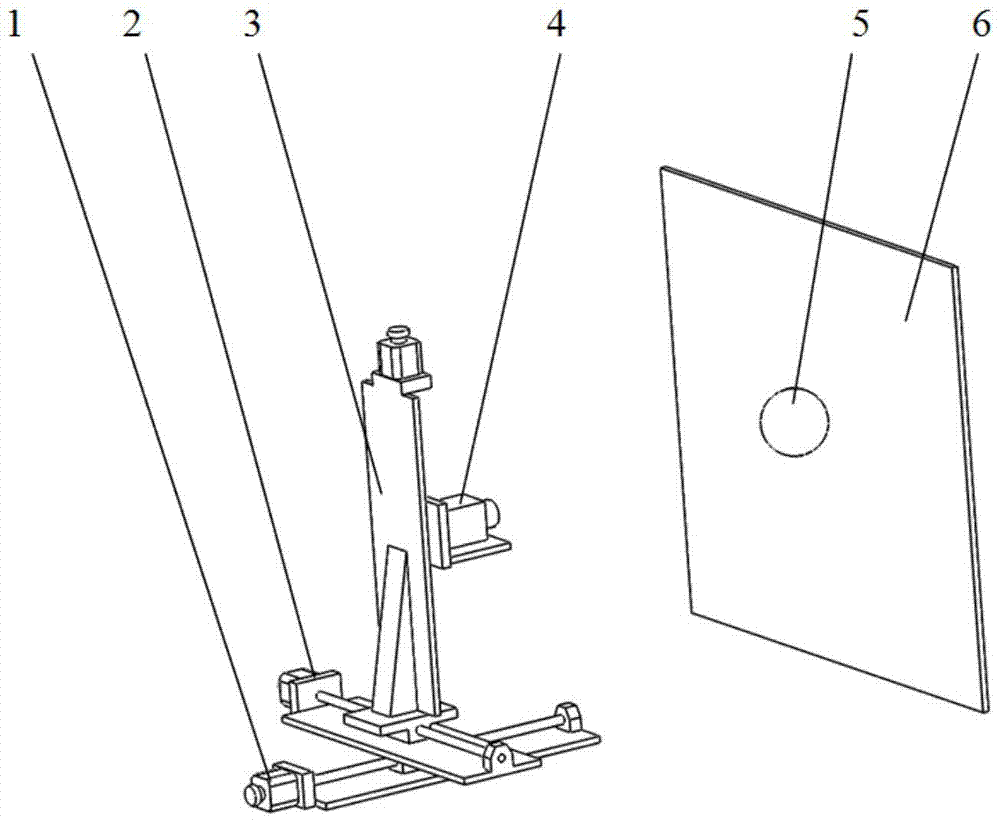
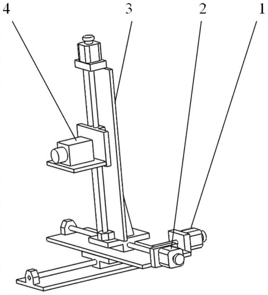
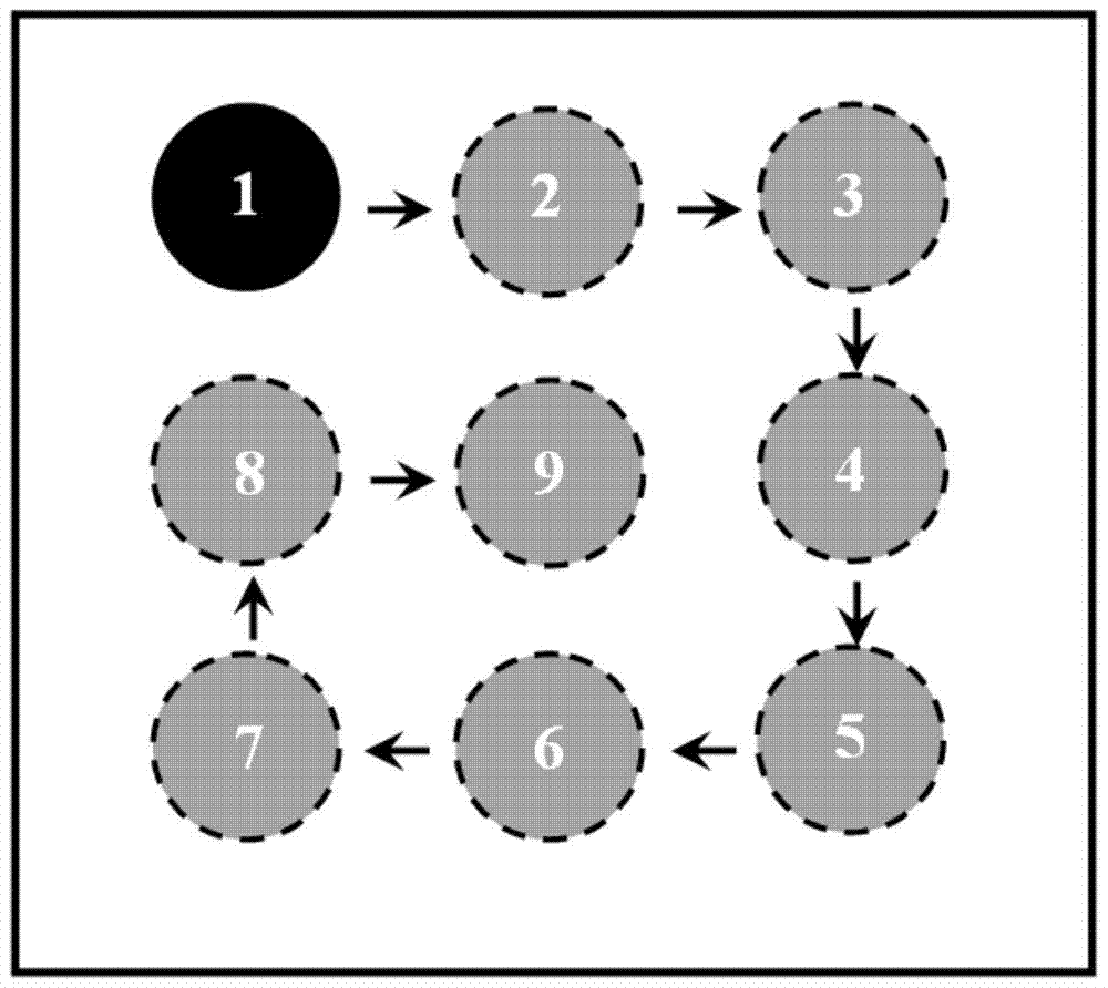
[0046] Taking the TOF depth camera 4 at a distance of 500 mm, the combination of the X-direction moving translation platform 2 and the Y-direction moving translation platform 3 to carry out 3×3 movement in the XY plane for three-dimensional coordinate calibration as an example, describe in detail the calibration device introduced in the present invention and Methods as below:

[0047] (1) First determine the space coordinate system OXYZ, the three translation axes of the three-dimensional translation platform are defined as the three directions of X, Y, and Z, the coordinate origin O is positioned as the lens center of the TOF depth camera 4, and the bottom surface of the three-dimensional motion translation platform is defined as The XZ plane is parallel to the installation bottom surface of the TOF depth camera 4; the Z direction is the optical axis direction of the TOF depth camera 4, and is parallel to the movement direction of the translation axis of the translation platfo...

Embodiment 2

[0059] Such as Image 6 As shown, the spherical target 5 is a target with more than 50% of the whole part having a spherical shape, and the other components and working principles of this embodiment are the same as those of the first embodiment.

[0060] In a word, the present invention reduces the difficulty and measurement error of a single TOF depth camera for the center point feature recognition of a spherical target, effectively improves the three-dimensional measurement accuracy of the TOF depth camera, and can flexibly set the center position and number of virtual standard spheres, making it easy to Realize the whole process of high-precision automatic calibration.


PUM


Abstract

The invention relates to a three-dimensional coordinate calibration device and a method of a TOF (Time-of-Flight) depth camera based on sphere center positioning of virtual multiple spheres. The device comprises a three-dimensional motion translation table, the TOF depth camera, a sphere target and a background board. Anisotropic invariance of the sphere target at different measurement angles is fully used and three mutually orthogonal one-dimensional motion translation tables generate several motions in a three-dimensional direction to form a virtual multi-sphere target with complicated shape; the target does not generate a multi-surface characteristic at the different measurement angles of the TOF depth camera; high-accuracy positioning on the center of the target is facilitated; and three-dimensional coordinate calibration of the TOF depth camera can be realized after a three-dimensional coordinate measurement value and a spatial position of a sphere center of the virtual multi-sphere target are obtained. The device reduces the characteristic recognition difficulty and a measurement error of a center point of the sphere target for the TOF depth camera for one time; the three-dimensional measurement accuracy of the TOF depth camera is effectively improved; center positions and the number of virtual standard spheres can be flexibly set; and overall-process high-accuracy automatic calibration is easy to realize.

Description

technical field [0001] The invention belongs to the technical field of optical metrology and calibration, and in particular relates to a calibration device and method for a non-scanning laser three-dimensional TOF (Time-of-Flight) depth camera positioned at the center of a virtual multi-sphere. Background technique [0002] With the improvement and improvement of optical measurement and computer vision technology, the development of advanced manufacturing technology and the diversification of product requirements, the demand for measurement of three-dimensional shape information on the surface of complex objects continues to grow. As a new generation of optical three-dimensional measurement technology, the TOF depth camera can obtain the grayscale information of space objects and the depth information corresponding to each pixel in real time. It has the advantages of good real-time performance, moderate measurement accuracy, small size, and light weight. It is used in the na...

Claims


Application Information

Patent Timeline
Patent Type & Authority Patents(China)
IPC IPC(8): G01C25/00G01M11/00
CPCG01C25/00G01M11/00
Inventor 敖磊刘永奇董鑫熊胜军
Owner ACAD OF OPTO ELECTRONICS CHINESE ACAD OF SCI
Why Eureka
Try Eureka