Online detection device and method for polarization axis alignment in direct coupling process of polarization-preserving fiber ring and Y waveguide

A polarization-maintaining optical fiber ring and detection device technology, applied in the direction of measuring devices, optical devices, instruments, etc., can solve the problems of affecting the axis-to-axis accuracy of the polarization axis, increasing the polarization cross-coupling of the waveguide output channel, and reducing the reliability of the system. Achieve high alignment accuracy and improve the effect of shaft alignment accuracy

Inactive Publication Date: 2015-01-28
BEIHANG UNIV
View PDF5 Cites 28 Cited by
  • Summary
  • Abstract
  • Description
  • Claims
  • Application Information

AI Technical Summary

Problems solved by technology

The problem of this Y-waveguide pigtail and polarization-maintaining fiber ring optical fiber connection method is that two fusion points are introduced between the Y-waveguide and the polarization-maintaining fiber ring, which reduces the reliability of the system; at the same time, the presence of fusion points increases the The polarization cross-coupling of the waveguide output channel reduces the detection accuracy of the system; and fusion splicing requires a certain length of fiber, which not only reduces the consistency of the assembly process of the optical path, but also easily destroys the quadrupole symmetry of the fiber ring
[0010] 1. When the first pigtail assembly of the fiber optic ring is coupled with the Y waveguide, if the polarization axis alignment is performed by directly measuring the extinction ratio method, the extinction ratio tester needs to be connected to the polarization maintaining during the coupling process of the fiber optic ring pigtail assembly and the Y waveguide At the other end of the fiber ring, due to the high polarization crosstalk of the polarization-maintaining fiber ring itself, the resolution of the observation results is low, which in turn affects the alignment accuracy of the polarization axis
[0011] 2. When the second pigtail assembly of the fiber optic ring is coupled with the Y waveguide, the optical path formed by the Y waveguide and the polarization-maintaining fiber ring is in a closed state, and the polarization axis alignment operation cannot be completed by detecting the extinction ratio of the output end
[0012] At the same time, the completion of the polarization axis alignment in the existing direct coupling technology depends on the machining accuracy of the fixture and the geometric dimension relationship between the mechanical parts, which makes it impossible to monitor the relative position of the polarization axis of the Y waveguide and the polarization maintaining fiber ring fiber in real time, thus Unable to quantitatively evaluate final state of polarization axis alignment

Method used


Image

  • Online detection device and method for polarization axis alignment in direct coupling process of polarization-preserving fiber ring and Y waveguide
  • Online detection device and method for polarization axis alignment in direct coupling process of polarization-preserving fiber ring and Y waveguide
  • Online detection device and method for polarization axis alignment in direct coupling process of polarization-preserving fiber ring and Y waveguide

Examples


Embodiment 1

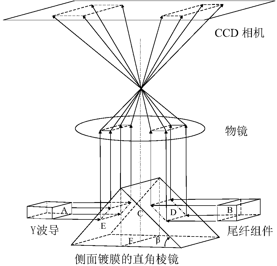
[0056] The specific structure of the imaging system is as follows: image 3 As shown, as follows:

[0057] The reflective optical element is a high-precision right-angle prism coated with a high-reflection film, which can be replaced by a rotating mirror or a double-sided mirror, which plays the role of refracting the optical axis.

[0058] When building the optical path of the polarization axis detection device, the Y waveguide, the polarization-maintaining fiber ring pigtail assembly, the imaging system and the CCD camera are coaxially arranged. The specific settings are: the right-angle prism is placed between the end face A of the Y waveguide and the end face B of the pigtail assembly of the polarization-maintaining fiber ring, with the bottom surface F of the right-angle prism as the reference plane, the reference plane C of the right-angle prism is perpendicular to the bottom surface F of the prism, and the reference plane C Keep parallel to the end face A of the Y-wave...

Embodiment 2

[0071] The rectangular prism is replaced by a double-sided mirror, and the specific structure is as follows:

[0072] like Figure 4 As shown, the Y waveguide, the polarization-maintaining fiber ring pigtail assembly and the double-sided reflector are coaxially arranged. The double-sided reflector is placed between the two ends of the Y-waveguide and the polarization-maintaining fiber ring pigtail assembly. The two working surfaces correspond to The end face of the Y waveguide and the end face of the polarization-maintaining fiber ring pigtail assembly; two sets of objective lenses are used to image the end face of the Y waveguide and the end face of the polarization-maintaining fiber ring pigtail assembly respectively, wherein each objective lens corresponds to a CCD camera, and the two CCD cameras are respectively It is used to collect images of two end faces, and transmit the collected images of both end faces to the computer for processing.

[0073] Specifically, the ligh...

Embodiment 3

[0077] The rectangular prism is replaced by a rotating mirror, and the specific structure is as follows:

[0078] like Figure 5 As shown, the Y waveguide, the polarization maintaining fiber ring pigtail assembly and the rotating mirror are coaxially arranged, and the rotating mirror is placed between the two ends of the Y waveguide and the polarization maintaining fiber ring pigtail assembly; the working surface of the rotating mirror is a single reflecting surface , its rotation center line is perpendicular to the coaxial line connecting the center of the Y waveguide and the pigtail assembly of the polarization-maintaining fiber ring; the reflective surface has two position states of 1 and 2, and it is rotated by 90 from the other position state ° Obtained; respectively used to reflect the images of the Y waveguide end face and the polarization maintaining fiber ring pigtail assembly end face to the objective lens.

[0079] When the mirror is rotated to position 1, the ligh...


PUM


Abstract

The invention discloses an online detection device and method for polarization axis alignment in the direct coupling process of a polarization-preserving fiber ring and a Y waveguide. The polarization axis online detection device comprises a polarization axis detection device and an image processing module. The polarization axis detection device comprises an illumination system, an imaging system and a CCD camera. The imaging system comprises a reflective optical element and an objective lens, and is used for imaging and magnifying the end face of the Y waveguide and the end face of a tail fiber assembly of the tail the polarization-preserving fiber ring. The method comprises the steps that (1) the Y waveguide and the tail ring assembly of the polarization-preserving fiber ring are mounted, and the end face of the Y waveguide and the end face of the tail ring assembly of the polarization-preserving fiber ring are adjusted to be in parallel; (2) the imaging system is adjusted to enable the CCD camera to obtain a clear image; (3) the image is collected to a memory, and the deviation angle of the polarization axis of the Y waveguide and the fiber polarization axis of the polarization-preserving ring is acquired and calculated. According to the online detection device and method, the relative position information of the polarization axes of the polarization-preserving ring and the Y waveguide in the direct coupling process can be acquired in real time, quantitative evaluation can be made for the final state of the alignment of the polarization axes, and a foundation is laid for further improving the axis alignment precision.

Description

technical field [0001] The invention belongs to the field of optical fiber sensing, and relates to an on-line detection device and an on-line measurement method for directly coupling polarization axis alignment between a polarization-maintaining optical fiber ring and a Y waveguide. Background technique [0002] Fiber optic gyroscope is an all-solid-state pure optical inertial device, the basic principle is Sagnac effect and optical reciprocity. The optical path of the fiber optic gyro is mainly composed of optical devices, polarization-maintaining fiber rings and detectors. Among them, the optical device includes a broadband light source, fiber coupler and Y waveguide; the Y waveguide chip integrates a beam splitter, a polarizer and a broadband phase modulator, and plays the functions of light splitting / combining, polarizing / analyzing and optical phase modulation. It is an important part of the optical path. [0003] At present, the fiber optic gyro optical path is usuall...

Claims


Application Information

Patent Timeline
Patent Type & Authority Applications(China)
IPC IPC(8): G01B11/27G01C25/00
Inventor 杨德伟甄洪旭冯迪宋凝芳张芳杰
Owner BEIHANG UNIV
Why Eureka
Try Eureka