A mixed model capacitance multiplier circuit

A multiplication circuit and capacitance multiplication technology, applied in electrical components, impedance networks, networks using active components, etc., can solve the problems affecting circuit bandwidth, circuit area and power consumption increase, and achieve small circuit area, small power consumption. The effect of small consumption and small area

Active Publication Date: 2015-01-28
SUN YAT SEN UNIV +1
View PDF4 Cites 4 Cited by
  • Summary
  • Abstract
  • Description
  • Claims
  • Application Information

AI Technical Summary

Problems solved by technology

At the same time, the disadvantage of this structure is that the area and power consumption of the circuit will increase with the increase of the multiplication factor
This limitation makes this circuit usually only provid...

Method used


Image

  • A mixed model capacitance multiplier circuit
  • A mixed model capacitance multiplier circuit
  • A mixed model capacitance multiplier circuit

Examples


Embodiment Construction

[0035] The accompanying drawings are for illustrative purposes only and cannot be construed as limiting the patent;

[0036] In order to better illustrate this embodiment, some parts in the drawings will be omitted, enlarged or reduced, and do not represent the size of the actual product;

[0037] For those skilled in the art, it is understandable that some well-known structures and descriptions thereof may be omitted in the drawings.

[0038] The technical solutions of the present invention will be further described below in conjunction with the accompanying drawings and embodiments.

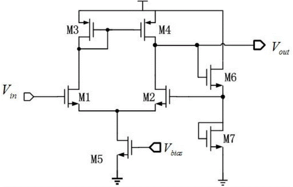
[0039] Such as image 3 , the voltage mode multiplier circuit unit is composed of CMOS tubes by M 1 , M 2 , M 3 , M 4 , M 5 , M 6 and M 7 composition. The M 1 , M 2 , M 3 , M 4 and M 5 constitutes a differential input operational amplifier loaded with a current mirror, the M 6 with M 7 Constitute a source follower structure, used as the feedback network of the amplifier. When t...


PUM


Abstract

The present invention discloses a mixed model capacitance multiplier circuit, which includes a voltage mode multiplication circuit unit and a current mode multiplication circuit unit; the voltage mode multiplication circuit unit includes an operational amplifier and a source follower, an input voltage signal is input to a positive input end of the operational amplifier, an output end of the operational amplifier is added to a negative input end of the operational amplifier via the source follower, and the output end of the operational amplifier is connected with the current mode multiplication circuit unit; the current mode multiplication circuit unit includes a capacitor C, a bias circuit of a high swing cascode current mirror and the high swing cascode current mirror, the output end of the operational amplifier is connected with one end of the capacitor C, the other end of the capacitor C is connected with the input end of the current mirror, and the output end of the current mirror is connected with an input voltage; and the bias circuit of the current mirror provides bias for the current mirror. The mixed model capacitance multiplier circuit of the present invention has the characteristics such as low power consumption, small area, input impedance at high and low frequencies and wide working bandwidth.

Description

technical field [0001] The invention relates to the field of capacitance multiplier circuits, in particular to a mixed-mode capacitance multiplier circuit with low power consumption, high and low frequency input impedance, wide operating bandwidth and small area. Background technique [0002] As a basic electronic component, capacitors are widely used in various analog systems. In some applications such as direct-current (DC-DC) converters, linear low-dropout converters (LDOs) and filters, large capacitances of tens of picofarads or even nanofarads may be required. If such a large capacitor is integrated in the chip, it will cause a great area loss, but the off-chip capacitor requires additional pins, which will increase the printed circuit board (PCB) area and design difficulty, and will introduce parasitic parameters, affecting the circuit. performance. Capacitance multiplier came into being to solve this kind of problem. Its biggest function is to build a circuit throu...

Claims


Application Information

Patent Timeline
IPC IPC(8): H03H11/00
Inventor 曾衍瀚谭洪舟唐伟杰李毓鳌陈荣军
Owner SUN YAT SEN UNIV
Why Eureka
Try Eureka