Energy-saving mineral wool preparation system with thermal-state slag

A preparation system, hot slag technology, applied in glass manufacturing equipment, manufacturing tools, etc.

Inactive Publication Date: 2015-02-04
宝钢矿棉科技(宁波)有限公司
View PDF4 Cites 0 Cited by
  • Summary
  • Abstract
  • Description
  • Claims
  • Application Information

AI Technical Summary

Problems solved by technology

The outer surface of the centrifugal roll of this application is smooth arc surface equally, and it also has above-mentioned deficiency

Method used


Image

  • Energy-saving mineral wool preparation system with thermal-state slag
  • Energy-saving mineral wool preparation system with thermal-state slag
  • Energy-saving mineral wool preparation system with thermal-state slag

Examples


Embodiment Construction

[0047] Below in conjunction with accompanying drawing and specific embodiment the present invention is described in further detail:

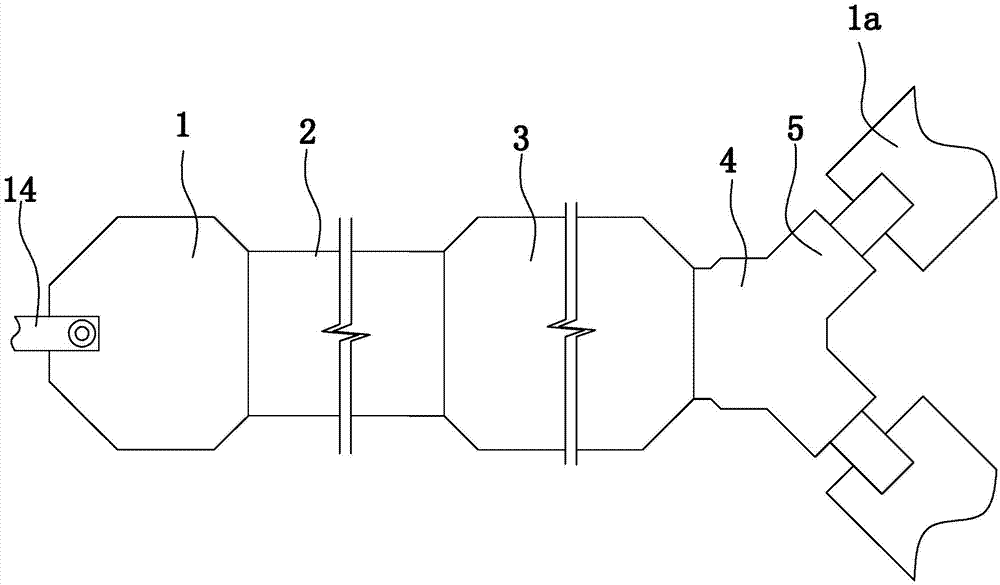
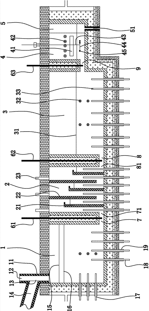
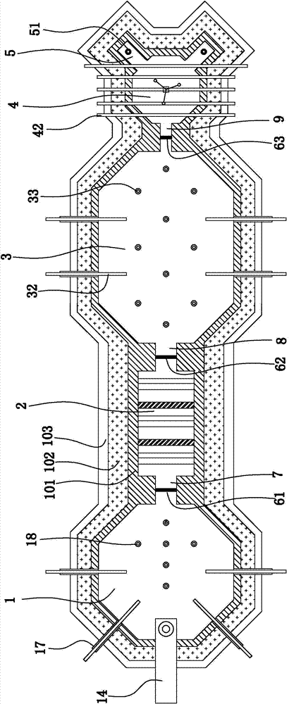
[0048] Such as figure 1 , figure 2 , image 3 As shown, an energy-saving mineral wool preparation system using hot slag includes a slag furnace and two or three or four centrifuges; there are two centrifuges in this embodiment. The slag furnace sequentially includes a feeding pool 1, a homogenizing pool 2, a melting pool 3, a purification pool 4 and two or three or four forehearths 5. Forehearth in the present embodiment is two. The number of centrifuges corresponds to (ie the same as) the number of forehearths. The bottom of the feeding tank and the bottom of the homogenizing tank are connected through a first flow channel 7 . The bottom of the homogenizing tank and the bottom of the melting tank are connected through the second flow channel 8 . The purification pool and the melting pool are connected through the third flow channel 9 . ...


PUM


Abstract

The invention discloses an energy-saving mineral wool preparation system with a thermal-state slag and aims to provide the energy-saving mineral wool preparation system which not only can fully utilize residual heat resources in blast furnace thermal-state slag and is energy-saving and environmental-protective but also can enable a melt in a slag furnace to be melted uniformly, a vitrification degree to be high and a fiber-forming ratio and quality of mineral wool to be improved. The device includes a slag furnace and at least two centrifugal machines. The slag furnace successively includes a feeding tank, a homogenizing tank, a melting tank, a clarifying tank and at least two material paths. A slag flow inlet and a main modulating material feeding port are arranged on an upper part of the feeding tank. The bottom of the feeding tank is connected to the bottom of the homogenizing tank through a first liquid flowing path. The bottom of the homogenizing tank is communicated with the bottom of the melting tank through a second liquid flowing path. The clarifying tank is communicated with the melting tank through a third liquid flowing path. One end of each material path is communicated with the clarifying tank and the other end of each material path is closed. In addition, material outlet ports are arranged at the bottoms of the material paths.

Description

technical field [0001] The invention relates to the field of mineral wool production, in particular to an energy-saving mineral wool preparation system utilizing hot slag. Background technique [0002] Mineral wool uses industrial waste slag (blast furnace slag, etc.) Under the action of the centrifugal force generated by the roller, it is thrown into mineral wool fibers; at the same time, the mineral wool fibers are blown into the cotton collector with the high-speed airflow ejected from the wind ring in the centrifuge (the high-speed airflow ejected from the air ring is on the centrifugal roller shaft. Upward, high speed flow along the surface of the centrifugal roller). The mineral wool fiber in the cotton collector gathers on the mesh belt of the cotton collector under the action of negative pressure wind suction to form a mineral wool felt. Mineral wool has the characteristics of light weight, small thermal conductivity, non-combustible, moth-proof, cheap, corrosion-r...

Claims


Application Information

Patent Timeline
Patent Type & Authority Applications(China)
IPC IPC(8): C03B37/005
CPCC03B37/005
Inventor 朱春江李胜春陈铁军王品益高晓骏沈健
Owner 宝钢矿棉科技(宁波)有限公司
Why Eureka
Try Eureka