Acquisition system and identification method of concrete surface initial crack information

A concrete surface and concrete technology, applied in the direction of optical devices, measuring devices, instruments, etc., can solve problems such as difficult to efficiently, objectively and accurately identify concrete, uneven strain distribution, unsuitable for high-strength and high-toughness concrete material measurement, etc.

Active Publication Date: 2015-02-04
ZHEJIANG UNIV
View PDF7 Cites 29 Cited by
  • Summary
  • Abstract
  • Description
  • Claims
  • Application Information

AI Technical Summary

Problems solved by technology

Moreover, because the strain distribution in the initial cracking area of ​​the concrete has significant inhomogeneity, and the strain gauge (strain gauge) can only reflect the average strain within the length range of the strain gauge (strain gauge), the strain gauge (strain gauge) cannot be accurately Identify the location of the first cracks in concrete
Correspondingly, since the strain gauge (strain gauge) cannot accurately characterize the strain value of the concrete, it cannot accurately identify the initial cracking time of the concrete
Due to the limitation of the stiffness of the strain gauge (strain gauge) itself, the strain gauge (strain gauge) is not suitable for the measurement of initial cracking of high-strength and high-toughness concrete materials
At the same time, since the strain gauges (strain gauges) often cannot be recycled for reuse during the test, the cost of the test is relatively high
[0004] Due to various defects in the technical principles and testing methods of using strain gauges (strain gauges) to test the initial cracking of concrete, it is difficult to efficiently, objectively and accurately identify information about the initial cracking of concrete

Method used


Image

  • Acquisition system and identification method of concrete surface initial crack information
  • Acquisition system and identification method of concrete surface initial crack information
  • Acquisition system and identification method of concrete surface initial crack information

Examples


Embodiment example

[0092] In reinforced concrete structures, steel corrosion is the main factor leading to concrete cracking. The cracking process of corroded reinforced concrete is simulated, and the invention is used to identify the initial cracking information of reinforced concrete.

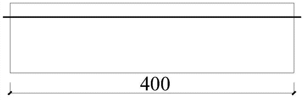
[0093] The mixing ratio of the concrete test is 1:0.53:2:3, followed by cement, water, fine aggregate, and coarse aggregate. The cement adopts P·052.5 grade ordinary Portland cement (382.8kg / m3) produced by Hubei Huaxin Cement Plant; the fine aggregate is river sand, the fineness modulus is 2.64; the coarse aggregate is crushed stone, 5-20mm continuous grade Match; water is tap water. The 28d compressive strength of concrete is 46.3MPa. The longitudinal bars are 10HPB235 steel bars, the size of the specimen is 100mm×100mm×400mm, and the thickness of the protective layer is 30mm. image 3 shown.

[0094] The speckle image on the surface of the sample is made by artificial method, because the humidity of the c...


PUM


Abstract

The invention relates to the technical field of construction material detection and aims to provide an acquisition system and identification method of concrete surface initial crack information. According to the method, the image of the surface of a concrete material piece to be tested is shot by a digital camera, then the digital image is processed and analyzed through a digital image matching method, finally the initial crack position of concrete is identified through a main strain distribution map peak point, and the initial crack time of the concrete is judged through the time change rule of the peak point strain. According to the acquisition system and identification method of concrete surface initial crack information, the influence of a strain gauge size effect can be effectively avoided, a strain gauge is not pasted to the surface of the concrete, and the initial crack position of the concrete surface can be accurately determined. All test equipment of the method is reproducible, the initial crack information of the concrete material can be objectively, accurately and reasonably identified, according to the method, the concrete sample treatment is simple, the operation is simple, the batch processing can be realized, a lot of manpower cost is saved, and the test cost is low.

Description

technical field [0001] The invention belongs to the technical field of building material detection, and in particular relates to a method for identifying the cracking position, cracking time and cracking strain of initial cracking of concrete surfaces based on digital image correlation technology. Background technique [0002] Concrete material is one of the most commonly used building materials in modern construction projects. It is very important to improve the service performance and durability of water-based concrete to improve the service life of building structures. However, due to the influence of various factors such as hydration heat release of cement-based materials, environmental erosion and loading, cracking is common in concrete structures. Since concrete cracking is one of the important reasons for the deterioration of the service performance and durability of concrete materials, it is also a research hotspot in the field of civil engineering. The initial cra...

Claims


Application Information

Patent Timeline
Patent Type & Authority Applications(China)
IPC IPC(8): G01B11/00G01B11/16
Inventor 金南国田野金贤玉童晶
Owner ZHEJIANG UNIV
Why Eureka
Try Eureka