Wave front coding imaging system focus plane position test method and device

A technology of wavefront coding and imaging system, which is applied in the direction of testing optical performance, etc., can solve the problem of inability to detect the wavefront coding system, etc., and achieves the effect of simple test operation, convenient use, and improved measurement accuracy.

Inactive Publication Date: 2015-02-04
DALIAN MARITIME UNIVERSITY
View PDF11 Cites 8 Cited by
  • Summary
  • Abstract
  • Description
  • Claims
  • Application Information

AI Technical Summary

Problems solved by technology

[0011] The present invention is aimed at the conventional detection method of determining the focal plane position according to the highest MTF position by detecting the modulation transfer function MTF (that is, the MTF at different positions) of the focus point, because the wavefront encoding system mak

Method used


Image

  • Wave front coding imaging system focus plane position test method and device
  • Wave front coding imaging system focus plane position test method and device
  • Wave front coding imaging system focus plane position test method and device

Examples


Embodiment

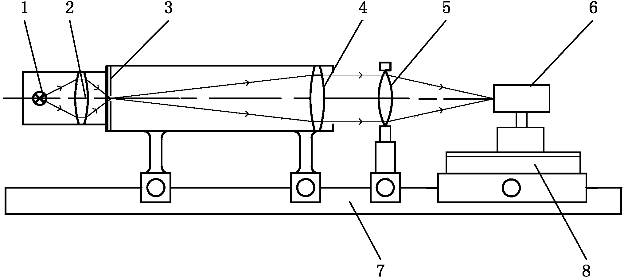
[0034] See attached figure 1 , which is a schematic diagram of the structure of the test device for the focal plane position of the wavefront encoding system in this embodiment, which is similar to the test device for the point spread function of the optical system. The test device consists of a light source 1 , a filter 2 , a star hole 3 , a collimating objective lens 4 , a measured wavefront encoding lens 5 , a detection camera 6 , an optical bench 7 , and a one-dimensional translation stage 8 . The light emitted by the light source 1 passes through the optical filter 2 to obtain monochromatic light, and then passes through the star point hole 3 and the collimating objective lens 4 to output parallel monochromatic light. After the parallel monochromatic light passes through the measured wavefront encoding system, the corresponding star point image is recorded by the CCD detector 6, and finally the phase transfer function is obtained through computer calculation. The CCD det...


PUM


Abstract

The invention discloses a wave front coding imaging system focus plane position test method. The wave front coding imaging system focus plane position test method includes following steps: firstly, shining monochromatic light which passes through start point holes on a camera lens which is to be tested and comprises a wave front coding phase plate; obtaining a star point image formed by the camera lens; then, confirming a pixel point of the maximum gray level in the star point image, intercepting all pixel points on a row where the pixel point of the maximum gray level is located, obtaining a one dimension point spread function, performing Fourier transformation on the point spread function, and obtaining a one dimension optical transfer function; finally, adjusting measurement positions of a camera which obtains the star point image, repeating the above steps so as to obtain optical transfer functions corresponding to different defocus positions, and calculating phase values of all the optical transfer functions at set spatial frequency; using all the phase values to perform data fitting so as to obtain a fitting curve, and using the highest point in the fitting curve as the position of a focus plane.

Description

technical field [0001] The invention relates to the testing of the focal plane position, in particular to a testing method and testing device for the focal plane position of a wavefront coding imaging system. Involving patent classification number G01 Measurement; Test G01M Test of static or dynamic balance of machines or structural parts; Test of structural parts or equipment not included in other categories G01M11 / 00 Test of optical equipment; Method Test Structural components G01M11 / 02 Test of optical properties. Background technique [0002] The wavefront encoding imaging system is a new type of optical imaging system. It adds a phase mask to the traditional optical system to encode the wavefront phase of the incident light wave, and obtains a blurred image that is not sensitive to defocus. The resulting blurred image is decoded to recover a clear image. [0003] The wavefront encoding imaging system increases the depth of field while ensuring the luminous flux and ima...

Claims


Application Information

Patent Timeline
IPC IPC(8): G01M11/02
Inventor 赵明许文海董丽丽吴厚德
Owner DALIAN MARITIME UNIVERSITY
Why Eureka
Try Eureka