A Distributed Series Coupled Power Flow Controller

A power flow controller and series coupling technology, applied in the direction of AC network circuits, electrical components, circuit devices, etc., can solve the problems of complex structure, high requirements, large footprint, etc., and achieve easy installation, compact structure, and low cost. Effect

Active Publication Date: 2017-01-11
STATE GRID CORP OF CHINA +2
View PDF1 Cites 0 Cited by
  • Summary
  • Abstract
  • Description
  • Claims
  • Application Information

AI Technical Summary

Problems solved by technology

However, FACTS equipment has many functions, complex structure, large floor area, high one-time investment cost, and high requirements for professional and technical personnel for daily operation management and maintenance. The current reliability of the system and other components is not very satisfactory

Method used


Image

  • A Distributed Series Coupled Power Flow Controller
  • A Distributed Series Coupled Power Flow Controller
  • A Distributed Series Coupled Power Flow Controller

Examples


Embodiment Construction

[0029] The present invention will be described in further detail below in conjunction with the accompanying drawings.

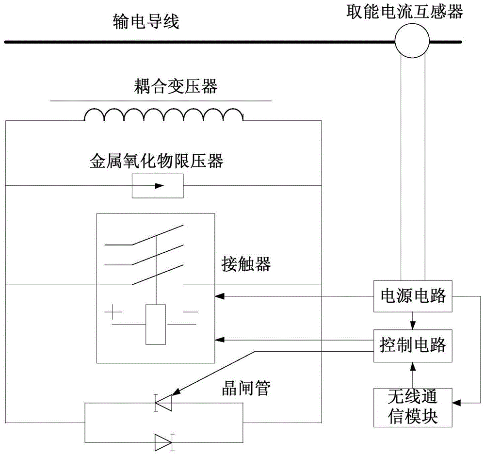
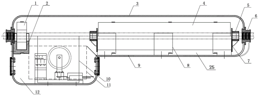
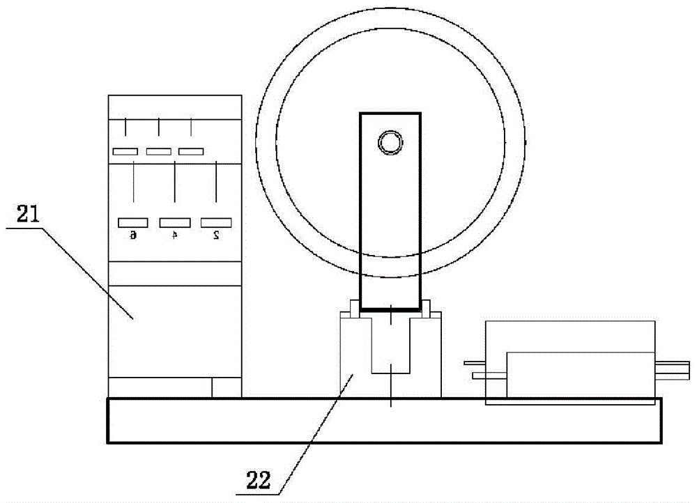
[0030] Such as figure 1 with figure 2 , the present invention provides a distributed series coupled power flow controller, the controller includes a control cabin 12, a coupling transformer cabin 25, an energy harvesting current transformer 1, an IGBT assembly 11, a control box 10 and a coupling transformer 4; The control cabin 12 and the coupling transformer cabin 25 are an integrated ladder structure, which is composed of an upper casing 3 and a lower casing 9 and can be opened and closed. The energy-taking current transformer 1, IGBT assembly 11 and control box 10 are installed in the In the control cabin 12, the coupling transformer 4 is installed in the coupling transformer cabin 25; the control cabin 12 and the coupling transformer cabin 25 are made of aluminum alloy.

[0031] The coupling transformer 4 is installed on the lower casing 9 of the coupl...


PUM


Abstract

The invention provides a distributed series-coupled type power flow controller comprising a control cabin, a coupling transformer cabin, a power-taking current transformer, an IGBT assembly, a control box and a coupling transformer, wherein the control cabin and the coupling transformer cabin are of an integral ladder structure, and the integral ladder structure consists of an upper shell and a lower shell and can be opened and closed; the power-taking current transformer, the IGBT assembly and the control box are arranged in the control cabin, and the coupling transformer is arranged in the coupling transformer cabin; and the control cabin and the coupling transformer cabin are made of an aluminum alloy material. According to the distributed series-coupled type power flow controller provided by the invention, insert of electrical reactance or capacitive reactance can be performed by virtue of a transformer coupling mode, a primary side winding of the coupling transformer is a single-turn power transmission line, and the coupling transformer is provided with a plurality of turns of secondary windings; the distributed series-coupled type power flow controller can perform rapid control by virtue of a solid-state combination switch, does not need to disconnect the power transmission line and change an original line structure, does not have space occupation requirements, achieves local control, is simple and flexible, is easy to assemble, can be repeatedly used in different lines, and can be used for greatly reducing the construction cost and running cost compared with a centralized FACTS device.

Description

technical field [0001] The invention relates to a controller, in particular to a distributed series coupled power flow controller. Background technique [0002] Flexible AC Transmission System (FACTS) is the product of the combination of modern power electronics technology and traditional power flow control technology, and it is a strong technical support for the traditional grid to move towards the smart grid. It uses high-power power electronic equipment to replace various traditional mechanical adjustment devices and high-voltage switches, so that the three main electrical parameters (voltage, line impedance and power angle) that affect the power flow distribution in the power system can be adjusted according to the instructions of the system dispatcher. Adjustment, realize the reasonable distribution of transmission power in the grid and the reasonable control of the voltage of each node, reduce power loss and power generation costs, and greatly improve the stability and...

Claims


Application Information

Patent Timeline
Patent Type & Authority Patents(China)
IPC IPC(8): H02J3/00
CPCH02J3/00H02J2203/20
Inventor 周亚娟赵刚段全新宋云东
Owner STATE GRID CORP OF CHINA
Why Eureka
Try Eureka