A multi-component layered submerged impinging flow reactor

An impinging flow reactor, multi-component technology, applied in chemical/physical/physical chemistry nozzle reactors, chemical methods for reacting liquids with liquids, chemical instruments and methods, etc., can solve the problem of not fully reflecting the advantages of impinging flow , to limit the application of impinging flow technology and the high cost of propeller manufacturing, to achieve the effect of improving the level of liquid micro-mixing, easy processing and high production efficiency

Active Publication Date: 2017-01-11
SHENYANG INSTITUTE OF CHEMICAL TECHNOLOGY
View PDF6 Cites 2 Cited by
  • Summary
  • Abstract
  • Description
  • Claims
  • Application Information

AI Technical Summary

Problems solved by technology

However, most of the current impinging flow reactors are equipped with a propeller structure in the guide tube. Although the mixing efficiency is improved, there are still some shortcomings, such as the high manufacturing cost of the propeller, and the long-term operation is easy to wear and tear.
Although the traditional impingement flow reactor has a good mixing effect in the impact area, the mixing effect is poor or even impossible in the area outside the impact area.
However, most of the existing impingement flow reactors formed by the impact of the jet flow are simple two-nozzle opposed type, the effective area of ​​the impact area is small, the processing capacity is limited, and the advantages of the impingement flow cannot be fully reflected, which limits the application of the impingement flow technology in the industrial field. application

Method used


Image

  • A multi-component layered submerged impinging flow reactor
  • A multi-component layered submerged impinging flow reactor

Examples


Embodiment

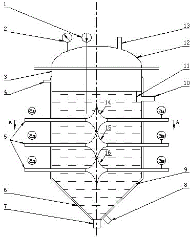
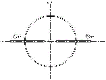
[0020] figure 1 It is a structural schematic diagram of the multi-component layered submerged impinging flow reactor (mixer) of the present invention.

[0021] In the figure: 1-thermometer, 2-pressure gauge, 3-kettle body, 4,8-heat exchange medium inlet and outlet, 5-feed inlet, 6-heating or cooling jacket, 7-outlet, 9- Conical bottom, 10-overflow port, 11-overflow weir, 12-top cover, 13-gas or steam outlet, 14,15,16-impact zone, (a)-(b) takeover position.

[0022] The present invention is composed of a kettle body 3, a feed pipe 5, a conical bottom 9, a top cover 12 and other parts, the main processing material is stainless steel, the shape of the kettle body 3 is a vertical cylinder, and the upper part adopts an oval head as the top cover 12. The lower part is a conical hollow cylinder, that is, the conical bottom 9, and the outer wall is provided with a heat exchange jacket 6. The top cover is provided with a gas outlet 13, a pressure gauge 2 and a thermometer 1, and the ...


PUM


Abstract

A multi-component layered submerged impingement flow reactor, which relates to a chemical reactor. The reactor adopts a multi-component layered structure, and the feed pipes are arranged on the kettle body in three layers: upper, middle, and lower. The feed pipes are coaxially opposed, and the nozzles with adjustable structure, diameter and spacing are installed at the outlet end of the feed pipe. The kettle body is a vertical cylindrical shape, with an oval top cover installed at the upper end, with a gas outlet, pressure gauge and thermometer socket, and a conical bottom with a discharge port at the lower end. An overflow outlet is provided on the side wall of the upper part of the kettle body, which can lead out the light components after reaction. A jacket is provided outside the tower wall for heating or cooling. When working, the fluid is sprayed out through the nozzle of the feed pipe, and violently collides in the collision zone of the kettle body to achieve the purpose of full mixing and reaction. )efficiency. The reactor can increase or decrease feed pipes in groups according to actual needs, adapt to various working conditions, easy to install, and low maintenance cost.

Description

technical field [0001] The invention relates to a chemical reactor, in particular to a multi-component layered submerged impingement flow reactor. Background technique [0002] In the process of reaction, reaction-precipitation and crystallization in the liquid-liquid phase and liquid-solid phase system, the mixing state in the reactor, especially the microscopic mixing state at the molecular scale, has an important influence on the reaction effect. At present, the most commonly used equipment in industry is the stirred tank reactor. The disadvantage of this kind of reactor is that the back mixing in the reactor is not uniform, and the stirring efficiency is low. The impinging flow reactor is a new type of chemical reaction equipment. Compared with the traditional stirred tank reactor, it has the advantages of large material contact area and high heat and mass transfer efficiency. However, most of the current impinging flow reactors are equipped with a propeller structure i...

Claims


Application Information

Patent Timeline
Patent Type & Authority Patents(China)
IPC IPC(8): B01J8/08B01J14/00B01J19/26
CPCB01J8/0085B01J8/085B01J8/087B01J14/00B01J19/26
Inventor 张建伟马红越冯颖董鑫
Owner SHENYANG INSTITUTE OF CHEMICAL TECHNOLOGY
Why Eureka
Try Eureka