Multi-functional molding machine for air hoses

A forming machine and multi-functional technology, applied in the direction of feeding device, positioning device, storage device, etc., can solve the problems that the diameter of the pipe collar cannot be adjusted, the metal plate cannot be smoothly exported, and the bending degree of the hoop bar cannot be adjusted. , to achieve the effect of simplifying the machine structure and operation process, compact structure and simple structure

Active Publication Date: 2015-02-18
江苏盛剑环境设备有限公司
View PDF5 Cites 3 Cited by
  • Summary
  • Abstract
  • Description
  • Claims
  • Application Information

AI Technical Summary

Problems solved by technology

However, the current rounding machine still has the following problems: 1. After the metal sheet is put in from one side of the upper roller and the lower roller, when the metal sheet comes out from the other side of the upper roller and the lower roller, it is easy to appear metal 2. The bearing sleeve set outside the feed roller shaft will rotate with the rotation of the feed roller shaft during the rotation of the feed roller shaft, causing the bearing sleeve The friction force between the parts in contact with its surroundings is too large, which makes the machine prone to accelerated aging due to wear and tear; 3. When the hoop machine is making the hoop strips, the curvature of the hoop strips cannot be adjusted, resulting in the inability to adjust the forming diameter of the pipe hoops, thus Limit the range of use of the hoop machine
[0004] The existing shrimp elbow machine is bulky and cumbersome, which is not convenient for transportation. If it is necessary to change the pressing shape of the curved joint of the air duct, the shrimp elbow machine must be adjusted repeatedly, which makes the operation extremely inconvenient

Method used


Image

  • Multi-functional molding machine for air hoses
  • Multi-functional molding machine for air hoses
  • Multi-functional molding machine for air hoses

Examples


Embodiment Construction

[0027] The present invention will be described in further detail below in conjunction with the accompanying drawings.

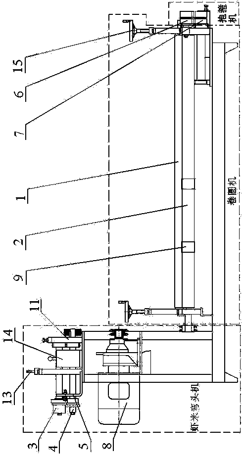
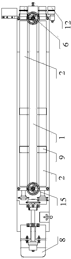
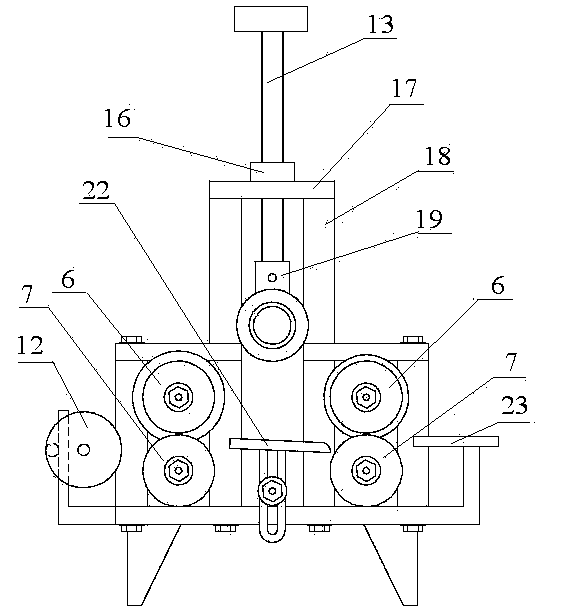
[0028] The structure of a multifunctional air duct forming machine of the present invention is as follows: Figure 1-4 As shown, it includes a rolling machine for bending and forming sheet metal parts, a shrimp elbow machine for connecting and forming dispersed curved duct segments, and a duct assembly for several segments composed of dispersed ducts. The connected hoop machine, the round machine, the shrimp elbow machine and the hoop machine are fixedly connected to each other. The rolling machine includes an upper pressing roller shaft 1 and a lower feeding roller shaft 2 arranged parallel to each other and rotatable, and the upper pressing roller shaft 1 is arranged in parallel above the lower feeding roller shaft 2; the dried shrimp elbow machine includes an upper die roller 3, The lower mold roller 4 and the limit baffle 5 used to limit the position of ...


PUM


Abstract

The invention discloses a multi-functional molding machine for air hoses. The molding machine comprises a rolling machine, a shrimp bending machine and a hooping machine, wherein the rolling machine is used for bending and molding a mental plate; the shrimp bending machine is used for connecting and molding scattered curved air hose segments; the hooping machine is used for connecting a plurality of air hose components constituted by scattered air hoses. Through the adoption of the molding machine, the bending and molding of the air hoses, the connecting and molding of the curved segments of the air hoses and the connecting of the air hose components can be completed at a time, so that the machine structure and the operation procedure are greatly simplified; by arranging caterpillar bands on a feeding roller, the phenomenon that the mental plate is propped against a lower roller is effectively eliminated, so that the mental plate can be smoothly guided out; the structural arrangement of the shrimp bending machine realizes that when the suppressing shapes of the end parts of the curved segments of the air hoses need to be changed, the shrimp bending machine is not needed to be complexly adjusted, and two kinds of shapes required can be achieved by simply veering or reversing a motor through pressing; the molding machine is compact in structure, smaller in size and convenient to be taken to a construction field for use, the transportation cost is greatly reduced, and the working efficiency can be effectively improved.

Description

technical field [0001] The invention discloses a forming machine, in particular to an air duct forming machine. Background technique [0002] The air duct forming process includes the steps of bending the sheet metal and connecting the curved part of the air duct. In the prior art, there are rolling machines for bending the sheet metal and connecting and forming the curved part of the air duct. However, because the two machines work independently of each other, the process of forming the air duct is cumbersome, and the pipe hoop cannot be formed at one time. [0003] At present, most of the general rolling machines process the plate with three rollers at the same time. The three rollers are arranged in the shape of a character, and the metal plate is placed between the upper roller and the lower two rollers. , under the pressure of three rollers, the metal sheet is bent into shape. However, the current rounding machine still has the following problems: 1. After the metal ...

Claims


Application Information

Patent Timeline
Patent Type & Authority Applications(China)
IPC IPC(8): B21D51/16B21D5/14B21D39/04B21D43/08B21D53/16
Inventor 姚建忠
Owner 江苏盛剑环境设备有限公司
Why Eureka
Try Eureka