A fiberglass antenna cover cutting equipment

A cutting equipment and glass fiber reinforced plastic technology, which is applied in metal processing, smoke removal, cleaning methods and utensils, etc., can solve the problems of poor product accuracy, affecting the work efficiency of the assembly process, and low work efficiency.

Active Publication Date: 2016-04-13
ZHEJIANG E STRONG COMM TECH
View PDF3 Cites 0 Cited by
  • Summary
  • Abstract
  • Description
  • Claims
  • Application Information

AI Technical Summary

Problems solved by technology

[0005] The technical problem solved by the present invention is that, in the prior art, the FRP antenna cover is hand-laid and demolded with molds of different specifications during the manufacturing process, and the operator needs to measure the cutting of the four sides of the FRP cover first Length, ensure verticality, and then use a portable electric cutting machine to complete the cutting operation, resulting in a long production and processing cycle and low work efficiency. Operators often need to use a portable electric grinder to polish the edges that do not meet the verticality requirements. Repeated grinding and correction part by part will seriously affect the work efficiency of the assembly process, and the product accuracy will be poor. At the same time, when cutting the burrs of the FRP antenna cover, a large amount of powder will splash, and the operator will easily inhale some of the flying particles into the body, seriously injuring the operator's body. Physical health, poor operating environment and not green environmental protection, and then provides a fiberglass antenna cover cutting equipment with optimized structure

Method used


Image

  • A fiberglass antenna cover cutting equipment
  • A fiberglass antenna cover cutting equipment
  • A fiberglass antenna cover cutting equipment

Examples


Embodiment Construction

[0024] The present invention will be further described in detail below with reference to the embodiments, but the protection scope of the present invention is not limited thereto.

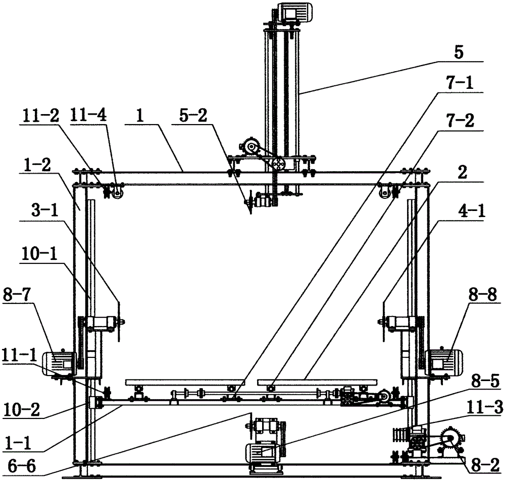
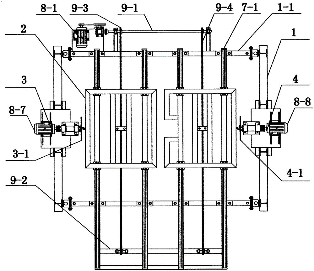
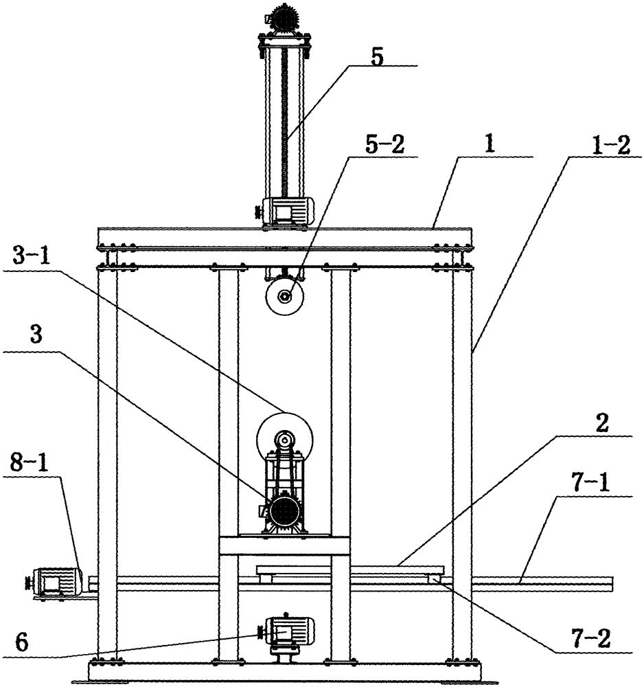
[0025]As shown in the figure, the present invention relates to a glass fiber reinforced plastic antenna cover cutting equipment, the cutting equipment includes a cutting base 1, and the cutting base 1 includes a transverse fixing rod 1-1 and a longitudinal fixing rod 1-2 arranged in cooperation, The horizontal fixing rod 1-1 and the longitudinal fixing rod 1-2 are matched with a working platform lifting mechanism; the lateral fixing rod 1-1 is provided with a working platform 2, and the working platform 2 passes through the horizontal set in the front and rear directions. The displacement mechanism is arranged in cooperation with the transverse fixing rod 1-1; the left and right sides of the cutting base 1 are respectively provided with a left cutting mechanism 3 and a right cutting mechanism 4, and...


PUM


Abstract

The invention relates to outer hood cutting equipment for a glass epoxy antenna. The equipment comprises a cutting base which is provided with a lateral fixing rod and a vertical fixing rod in a fit manner, wherein a working platform elevating mechanism is arranged on the lateral fixing rod and the vertical fixing rod in a fit manner, a working platform is arranged on the lateral fixing rod, and the working platform and the lateral fixing rod are arranged in a fit manner through a lateral displacement mechanism which is arranged in a direction of front to back; a left cutting mechanism and a right cutting mechanism which are arranged on the same lateral height are respectively arranged on the left side and the right side of the cutting base; an upper cutting mechanism and a lower cutting mechanism are correspondingly arranged at the top and the lower part of the cutting base; the working platform elevating mechanism, the lateral displacement mechanism, the left cutting mechanism, the right cutting mechanism, the upper cutting mechanism and the lower cutting mechanism are connected to a control mechanism. Through the adoption of the cutting equipment disclosed by the invention, the production and processing cycle of the outer hood of the glass epoxy antenna is shortened, the working efficiency is improved, the precision of products is improved, the probability that when an operator cuts the burrs of glass-reinforced plastics, particles are sucked in the body of the operator is reduced, the human body of the operator is guanrateed to be healthy, and the operating environment is clean and environmental-friendly.

Description

technical field [0001] The invention belongs to the technical field of operation and control devices for machines or equipment used for cutting, cutting, punching, punching, punching or cutting by methods other than cutting, and particularly relates to a cutting device capable of cutting a glass fiber reinforced plastic antenna cover. Standardized and mechanized FRP antenna cover cutting equipment. Background technique [0002] In recent years, with the rapid development of the mobile communication industry, the requirements for the arrangement of base station antennas have become higher and higher, especially in urban rooftops, it is necessary to install antenna covers on the base station transmitting antennas. The common specifications of the current antenna cover include 600*600*1000(mm), 600*600*2000(mm), 700*700*1000(mm), 700*700*2000(mm), 800*800*1000(mm) ), 800*800*2000(mm) and other rectangular cylinders with a thickness of 4mm. [0003] In the selection of base st...

Claims


Application Information

Patent Timeline
Patent Type & Authority Patents(China)
IPC IPC(8): B26D1/16B26D7/26B26D7/02B08B15/00
Inventor 许雪灿高保证粟倡斌
Owner ZHEJIANG E STRONG COMM TECH
Why Eureka
Try Eureka