A Clutter Map Partitioning Method Based on Image Processing

An image processing and clutter map technology, applied in radio wave measurement systems, instruments, etc., can solve problems such as poor connectivity in clutter partition areas, unsuitable super clutter detection methods, and limited utilization of signal characteristic information, etc., to achieve Good operability and real-time performance, good effect, and improved connectivity

Active Publication Date: 2017-06-06
THE 28TH RES INST OF CHINA ELECTRONICS TECH GROUP CORP
View PDF3 Cites 2 Cited by
  • Summary
  • Abstract
  • Description
  • Claims
  • Application Information

AI Technical Summary

Problems solved by technology

[0009] (1) The clutter type is judged by the zero channel partition, which is used to determine the signal detection algorithm and detection threshold of all channels; the super clutter detection is often used in the zero channel ground clutter area, which can eliminate the ground clutter and improve the detection ability, but other channels The clutter characteristics of the corresponding area are no longer ground clutter characteristics, and the super clutter detection method is no longer suitable
[0010] (2) The existing clutter map partitions are updated based on signal amplitude fluctuations, the update method is single, and the use of signal characteristic information is limited
[0011] (3) Data fluctuations lead to poor connectivity in the clutter partition area, and too many discrete partition points bring more clutter background estimation errors

Method used


Image

  • A Clutter Map Partitioning Method Based on Image Processing
  • A Clutter Map Partitioning Method Based on Image Processing
  • A Clutter Map Partitioning Method Based on Image Processing

Examples


Embodiment 1

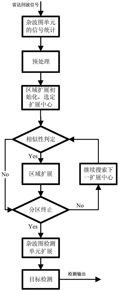
[0046] figure 1 It is the overall processing flow chart. , the radar echo signal goes through the stages of clutter map unit division, area expansion judgment, similarity judgment, clutter partition, clutter map detection, etc., to realize target detection processing. combine figure 1 , the embodiment method comprises the following steps:

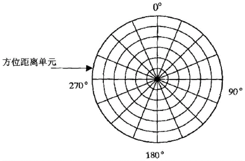
[0047] 1. According to the working mode and system parameters of the radar, calculate the radar range and beam width, and determine the division method and resolution unit of the clutter map. The division methods of the clutter map unit include equal sector division, equal area division and so on. Equal sector division is usually used, which is easy for hardware implementation. figure 2 is a schematic diagram of the division of clutter map units according to distance and azimuth.

[0048]2. Establishment and update of clutter map: Statistical clutter signal strength in the clutter map unit, which is the statistical average of the clut...


PUM


Abstract

The invention discloses a clutter map partitioning method based on imaging processing. The clutter map partitioning method includes steps of (1) calculating radar operating range and beam width and determining clutter map partitioning modes and resolution cells; (2) counting clutter signal strength in a clutter map unit and determining iteration coefficient; (3) subjecting clutter map data to median filtering and eliminating abnormal points having overlarge or too small estimated values by the median filtering; (4) partitioning a clutter map; (5) expanding a clutter map detecting unit, to be specific, simultaneously judging other eight units adjacent to one another in distance and direction when the clutter strength of the clutter unit is estimated, and finally subjecting the judgment results of the nine units to greatest selection processing as the final estimated value of the clutter scene; (6) detecting the clutter map, to be specific, expanding information by the clutter map detecting unit to form the clutter detecting threshold for radar target detection.

Description

technical field [0001] The invention relates to a method for partitioning a radar clutter map, in particular to a method for partitioning a radar clutter map based on image processing. Background technique [0002] Radar echoes not only include a large amount of target information, but also include ground clutter, sea clutter, weather clutter, interference and other information. When the radar is working, the clutter echo amplitude in the surrounding environment is usually stored in an orderly manner according to the two-dimensional plane of distance and azimuth, so as to establish a clutter map. The clutter map is used to store the background clutter power of each range-azimuth unit, and the estimated values ​​of different scanning periods are iteratively averaged to calculate the clutter background estimate. [0003] It is of great significance to establish radar echo clutter map and perform clutter division. The clutter partition has the following effects: [0004] (1)...

Claims


Application Information

Patent Timeline
Patent Type & Authority Patents(China)
IPC IPC(8): G01S7/36G01S7/41
CPCG01S7/36G01S7/411
Inventor 龙超赵春光黄绍斌欧乐庆王寿峰郑坚汪洋彭思付乾良朱栋章林王毅艳
Owner THE 28TH RES INST OF CHINA ELECTRONICS TECH GROUP CORP
Why Eureka
Try Eureka