An Optimal Design Method for the Link Mechanism of a Three-roller Guide

A link mechanism, optimization design technology, applied in the direction of calculation, special data processing applications, instruments, etc., can solve the problems of cumbersome design, programming, calculation process, non-consideration of nonlinear errors, large workload, etc.

Inactive Publication Date: 2018-02-27
HUBEI POLYTECHNIC UNIV
View PDF2 Cites 0 Cited by
  • Summary
  • Abstract
  • Description
  • Claims
  • Application Information

AI Technical Summary

Problems solved by technology

[0017] ① There is no in-depth discussion on the influence of the position of the hinge points D and G of the rocker and the length of the swing arm of the guide roller on the working performance of the mechanism, and no specific calculation method is given, but it is considered to be related to the structural design
[0018] ②Using the analytical method to analyze the mechanism, the design, programming, and calculation processes are cumbersome, the workload is heavy, and the working performance of the mechanism cannot be evaluated intuitively and conveniently
[0019] ③In the mechanism design process, only the centering accuracy is considered but the relationship between the stroke of the hydraulic cylinder I and the opening degree of the guide roller is not considered
Although such processing avoids cumbersome analytical derivation and reduces the amount of calculation of the control system, it does not consider the resulting nonlinear error; when the nonlinear error is too large to affect the adjustment of the opening, the operator needs to adjust the Proper correction of the situation will bring a lot of inconvenience to the calibration of the control system, the operation and maintenance of the equipment

Method used


Image

  • An Optimal Design Method for the Link Mechanism of a Three-roller Guide
  • An Optimal Design Method for the Link Mechanism of a Three-roller Guide
  • An Optimal Design Method for the Link Mechanism of a Three-roller Guide

Examples


Embodiment Construction

[0125] In order to make the object, technical solution and advantages of the present invention clearer, the present invention will be described in further detail below in conjunction with the accompanying drawings. It should be understood that the specific embodiments described here are only used to explain the present invention and are not intended to limit the present invention. .

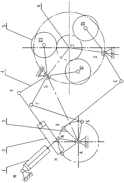
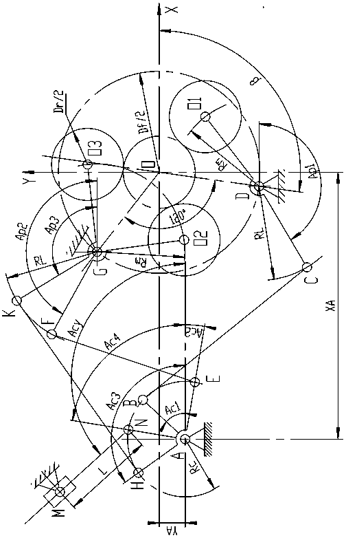
[0126] see figure 1 — Figure 5 , the present invention is a method for optimizing the design of the linkage mechanism of a three-roller guide, and the linkage mechanism includes ABCDO 1 、AEFGO 2 and AHKGO 3 A total of 3 sets of four-bar mechanisms, of which AEFGO 2 and AHKGO 3 The racks are the same, the cranks 3AB, AE, and AH of each group of four-bar mechanism are equal in length and are the same member, and the cranks AB, AE, and AH can swing around the hinge point A under the action of hydraulic cylinder I. The lengths of rocker 4 are equal, that is, CD=FG=KG, the hinge points D and G ...


PUM


Abstract

The present invention is a method for optimizing the design of the linkage mechanism of a three-roller guiding device. The method takes the maximum and minimum openings of the three guide rollers, the diameter of the guide roller and the stroke of the hydraulic cylinder I as the known conditions, and according to the Based on the principle that the motion track tends to be symmetrical with respect to the rolling center, the position of the hinge point of the rocker and the length of the swing arm of the guide roller are determined; then the hydraulic cylinder II with the fully extended piston rod is regarded as a connecting rod, and the position of the hinge point of the mechanism crank and the length of the swing arm of the guide roller are determined. The size of each rod is a design variable, so that the stroke of the hydraulic cylinder I and the opening of the guide roller tend to be linear, and the center of the inscribed circle of the guide roller tends to the rolling center as the optimization target. Work and have good transmission characteristics to meet the conditions as constraints, establish an optimal design mathematical model, establish a virtual prototype model through ADAMS and use the main objective method to complete the optimization solution, and then perform a simulation test on the optimized mechanism to determine the final Institutional parameters.

Description

technical field [0001] The invention relates to the technical field of production of hot-rolled seamless steel pipes, in particular to an optimal design method of a three-roller guiding device connecting rod mechanism used at the exit of a cross-rolling piercing machine or at the entrance of a cross-rolling pipe rolling mill. Background technique [0002] There are several three-roll guide devices along the rolling direction at the exit of the cross-rolling piercer. The three guide rollers of each guide device clamp the ejector rod during the piercing process, so that the top of the front end of the ejector rod is located in the middle of the roll gap of the piercer. ensure that its center line coincides with the rolling center line, and prevent the ejector rod from being destabilized under pressure during the piercing process; when the capillary is extended, each guide device loosens the ejector rod in sequence with the movement of the front end of the capillary, limiting th...

Claims


Application Information

Patent Timeline
Patent Type & Authority Patents(China)
IPC IPC(8): G06F17/50
Inventor 张轶蔚邓彬伟严伟汤立刚
Owner HUBEI POLYTECHNIC UNIV
Why Eureka
Try Eureka