
Wind power generation system

A technology of wind power generation system and wind power generator, which is applied in the direction of wind power generation, electrical components, circuit devices, etc., and can solve problems such as damage to power devices, system failure shutdown, and DC bus voltage rise

Inactive Publication Date: 2015-02-18
STATE GRID CORP OF CHINA +4
View PDF1 Cites 4 Cited by
  • Summary
  • Abstract
  • Description
  • Claims
  • Application Information

AI Technical Summary

Problems solved by technology

[0005] The purpose of the present invention is to provide a wind power generation system to solve the problem that the rise of the DC bus voltage may cause the system to shut down and destroy the power devices

Method used


Image

  • Wind power generation system
  • Wind power generation system
  • Wind power generation system

Examples


Embodiment Construction

[0015] The present invention will be further described in detail below in conjunction with the drawings.

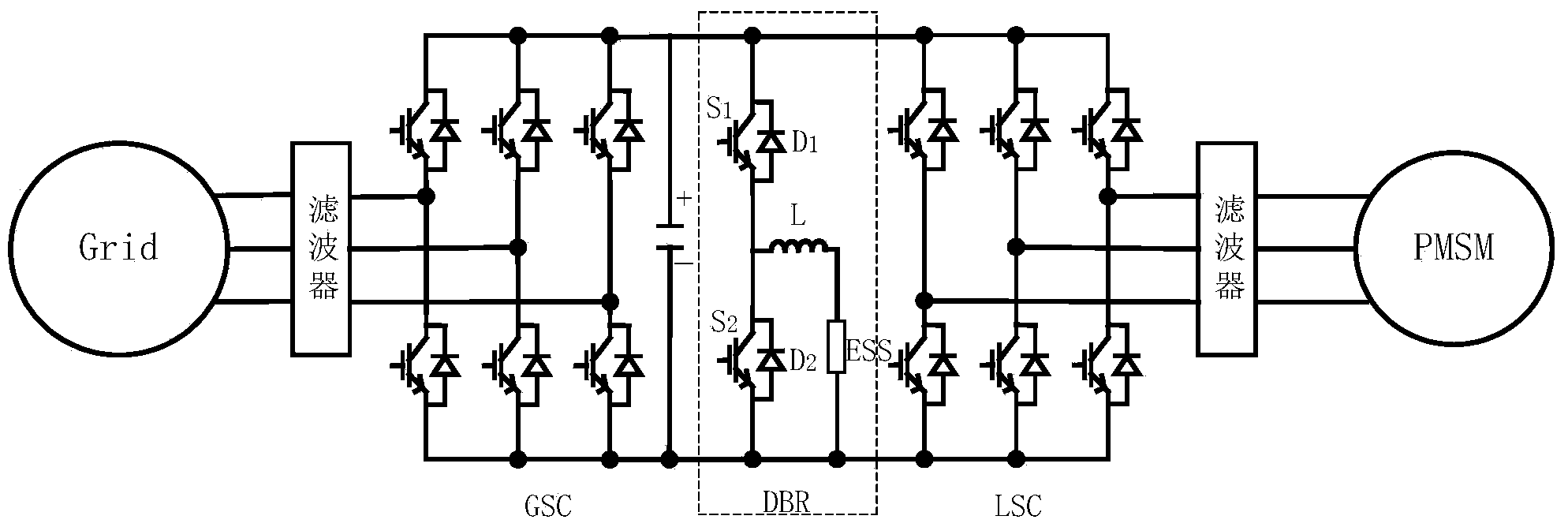
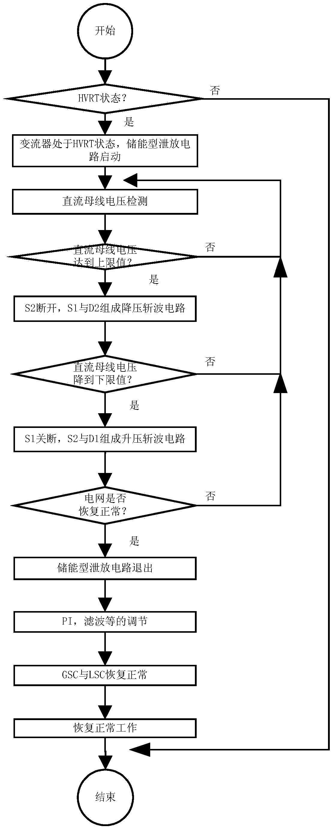
[0016] The present invention is a wind power generation system, which includes a wind generator, a machine-side converter, a DC bus and a grid-side converter connected in sequence. The grid-side converter is used to connect to the power grid. A capacitor is connected to the DC bus. An energy storage type bleeder circuit is also connected to the bus bar. The energy storage type bleeder circuit includes a first switching element and a second switching element connected in series in sequence. The first switching element is connected in reverse parallel to the first diode, and the second switching element The second diode is connected in anti-parallel, and the second switching element is also connected in parallel with an inductor and resistor series branch.

[0017] When the voltage value of the DC bus reaches the first set value, the second switching element is turned off, and t...


PUM


Abstract

The invention relates to a wind power generation system comprising an energy-storage leakage circuit. The energy-storage leakage circuit is composed of two switching elements each provided with antiparallel diodes, an inductor and a resistor. When the fact that voltage of a direct current bus is greater than set highest voltage is detected, the second switching element in the energy-storage leakage circuit is switched off, the first switching element and a second diode form a buck chopper circuit, and direct-current voltage is lowered after the inductor absorbs surplus energy; when the voltage of the direct current bus drops to allowable lowest voltage, the first switching element is switched off, the second switching element and a first diode form a boost chopper circuit, and energy stored in the inductor is released to assist in restoring a normal value of the voltage of the direct current bus. The switching elements of the energy-storage leakage circuit are subjected to alternate chopper control, energy leakage and voltage stability control of the direct current bus during high voltage ride-through can be achieved, and the voltage of the direct current bus can be assisted in restoring fast after dropping, by releasing the energy from the inductor.

Description

Technical field [0001] The invention relates to a wind power generation system, belonging to the technical field of wind power generation. Background technique [0002] In recent years, offshore wind power and land wind power have developed rapidly, and installed capacity has increased year by year. Direct-drive wind turbines that use permanent magnet synchronous motors as generators can eliminate the speed-increasing gearboxes of doubly-fed wind turbines, reducing the volume and size of the generators. Weight can also reduce noise and maintenance costs, and has been more and more widely used. With the rapid development of wind power, the scale of wind power connected to the grid has become larger and larger, and the impact of the volatility of the wind power system has become more and more obvious, such as voltage fluctuations, power imbalances, and large harmonic content. , Affecting the stable operation of the power system. [0003] Among the published Chinese national standar...

Claims


Application Information

Patent Timeline
IPC IPC(8): H02J3/38
CPCH02H9/045H02J3/28H02J3/386Y02E10/76
Inventor 郜亚秋肖鹏刘刚孙健梁燕高亚春岳巍澎朱斯程林志杨杨史航卢仁宝
Owner STATE GRID CORP OF CHINA
Learn More