Rubber gasket lower pin

A technology of aprons and straight parts, which is applied in the field of lower pins of aprons in the drafting mechanism of spinning frame, and can solve the problems of weakening the strength of the friction boundary in the middle of the main drafting area and weak elastic force of supporting aprons.

Inactive Publication Date: 2015-02-25
韦莉
View PDF0 Cites 1 Cited by
  • Summary
  • Abstract
  • Description
  • Claims
  • Application Information

AI Technical Summary

Problems solved by technology

[0002] At present, the drafting mechanism of the ring spinning machine in the spinning mill generally adopts long and short double rubber rings, spring swing pins, spring cradle pressurization, leaf spring cradle pressurization or pneumatic cradle pressurization devices, mainly relying on drafting rollers, Cots, aprons, elastic upper pins and curved surface stepped lower pins work together to control the fiber and realize drafting, and the intermediate additional friction force formed by the mechanism composed of the apron, elastic upper pin and curved surface stepped lower pin controls the movement of fibers , it plays a decisive role in ensuring the quality of the drafted sliver, especially the front jaw composed of the apron, elastic upper pin and curved surface stepped lower pin. The curved surface stepped lower pin mainly supports the lower apron and guides the lower apron to rotate stably. Support the upper pin so that it is in the position required by the process, and the lower pin is a six-spindle pin, which is fixed on the roller seat. The upper surface is a combination of a straight line and a curved line, and the curved

Method used


Image

  • Rubber gasket lower pin
  • Rubber gasket lower pin

Examples


Embodiment Construction

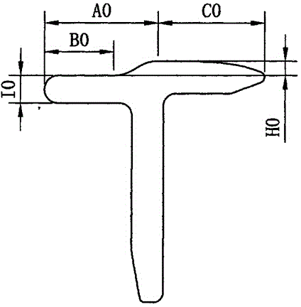
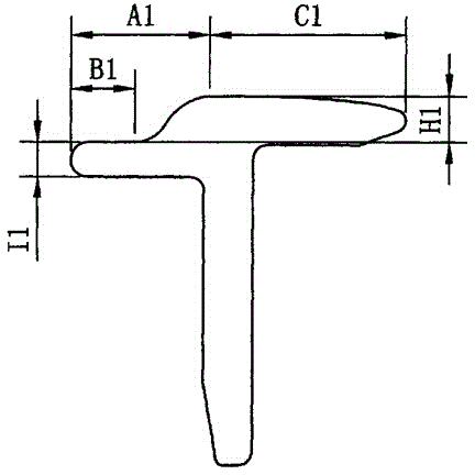
[0010] A kind of apron lower pin of the present application is an improved design carried out on the basis of the existing apron lower pin (see Fig. 1, 2). The shape of any cross-section is the same, which is basically T-shaped, and the upper surface of the T-shaped horizontal part is a combined shape connected by a straight line (plane) B and a curved line (curved surface). The curved part is higher than the straight part B, and the two The height difference between them is H, and the thickness of the straight line part B is I. Specifically, the structural shape and size of the lower pin of the apron in the prior art is: the distance AO between the highest point of the curved part and the front edge of the straight part is 13 millimeters, the length of the straight part B0 is 8 millimeters, and the highest point of the curved part is away from the lower pin of the apron. The distance CO of the tail end is 11 mm, the height difference H0 between the curved part and the straigh...


PUM

PropertyMeasurementUnit
Lengthaaaaaaaaaa
Thicknessaaaaaaaaaa
Lengthaaaaaaaaaa

Abstract

The invention discloses a rubber gasket lower pin. The shapes of any sections of the rubber gasket lower pin are the same, and the sections of the rubber gasket lower pin are basically in a T shape. The upper surface of the transversely linear part of the T shape is in a combination shape in which a straight line and a curved line are connected, the curved line part is higher than the straight line part, a height difference exists, the straight line part has a certain thickness, and the length of the straight line part is 4-4.9 millimeters. Correspondingly, the length of the curved line part which is connected with the straight line part is 20-19.1 millimeters, the distance from the highest point of the curved line part to the front edge of the straight line part is 9-9.9 millimeters, and correspondingly the distance C1 from the highest point to the tail end of the rubber gasket lower pin is 15-14.1 millimeters. The thickness of the straight line part is 2-5.3 millimeters, and correspondingly the height difference of the curved line part and the straight line part is 3.1-3.4 millimeters. The rubber gasket lower pin is simple in structure, convenient to mount and suitable for all existing ring spinning frames using curved face stair lower pins, the traction parts of the spinning frames do not need to be changed any more, and therefore the rubber gasket lower pin has wide applicability and economical efficiency.

Description

technical field [0001] The application relates to spinning drafting technology, in particular to the lower pin of the rubber ring of the drafting mechanism of spinning frame. Background technique [0002] At present, the drafting mechanism of the ring spinning machine in the spinning mill generally adopts long and short double rubber rings, spring swing pins, spring cradle pressurization, leaf spring cradle pressurization or pneumatic cradle pressurization devices, mainly relying on drafting rollers, Cots, aprons, elastic upper pins and curved surface stepped lower pins work together to control the fiber and realize drafting, and the intermediate additional friction force formed by the mechanism composed of the apron, elastic upper pin and curved surface stepped lower pin controls the movement of fibers , it plays a decisive role in ensuring the quality of the drafted sliver, especially the front jaw composed of the apron, elastic upper pin and curved surface stepped...

Claims


Application Information

Patent Timeline
IPC IPC(8): D01H5/88
CPCD01H5/88
Inventor 韦莉
Owner 韦莉
Why Eureka
Try Eureka