
Bottom wire detection control system and method based on optical fiber sensor and applied to industrial sewing machine

A technology of detection control system and optical fiber sensor, applied in sewing machine ferrule mechanism, bobbin winding in sewing machine, sewing machine components, etc., can solve the problem that photoelectric sensor is susceptible to external electromagnetic interference, and the sensitivity of photoelectric sensor is not high and cannot be judged. Missing bobbins and other problems can improve sewing efficiency and quality, strong anti-electromagnetic interference ability, and ensure uniformity and aesthetics.

Active Publication Date: 2015-02-25
BULLMER ELECTROMECHANICAL TECH
View PDF5 Cites 13 Cited by
  • Summary
  • Abstract
  • Description
  • Claims
  • Application Information

AI Technical Summary

Problems solved by technology

[0005] 1. When the bobbin is missing in the rotary hook, the receiver cannot receive the signal, which is exactly the same as when there is a bottom thread, so it cannot judge whether there is a missing bobbin;
[0006] 2. During the bottom line monitoring process, the photoelectric sensor is susceptible to external electromagnetic interference, and the sensitivity of the photoelectric sensor is not high, resulting in low bottom line monitoring accuracy and unreliable overall monitoring of the device;
[0007] 3. At some point, when the receiver receives the reflected light from the reflective surface of the bobbin winding post, the bobbin thread on the bobbin winding post has all been used up, so when the sewing machine stops and is replaced After the bobbin, there will be a stitch seam on the re-sewn material, resulting in unsightly or damaged sewing material

Method used


Image

  • Bottom wire detection control system and method based on optical fiber sensor and applied to industrial sewing machine
  • Bottom wire detection control system and method based on optical fiber sensor and applied to industrial sewing machine
  • Bottom wire detection control system and method based on optical fiber sensor and applied to industrial sewing machine

Examples


Embodiment Construction

[0063] The implementation of the present invention will be illustrated by specific specific examples below, and those skilled in the art can easily understand other advantages and effects of the present invention from the contents disclosed in this specification.

[0064] It should be noted that the structures, proportions, sizes, etc. shown in the drawings attached to this specification are only used to match the content disclosed in the specification, for those who are familiar with this technology to understand and read, and are not used to limit the implementation of the present invention. Limiting conditions, so there is no technical substantive meaning, any modification of structure, change of proportional relationship or adjustment of size, without affecting the effect and purpose of the present invention, should still fall within the scope of the present invention. The disclosed technical content must be within the scope covered. At the same time, terms such as "upper"...


PUM


Abstract

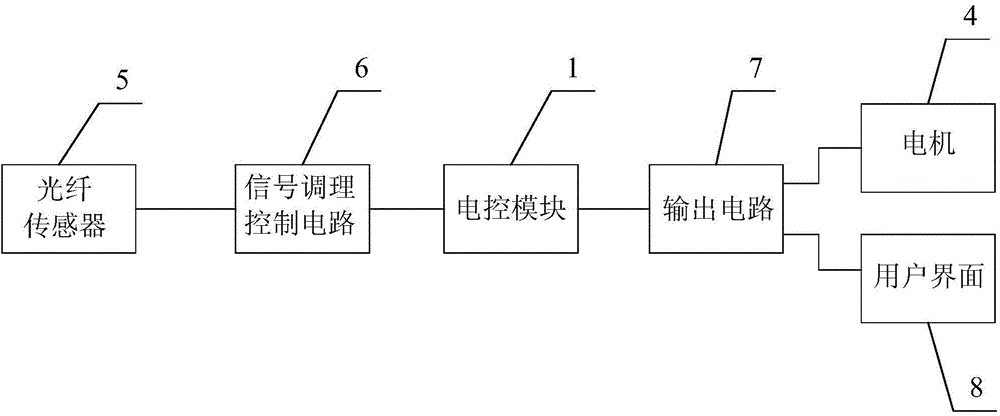
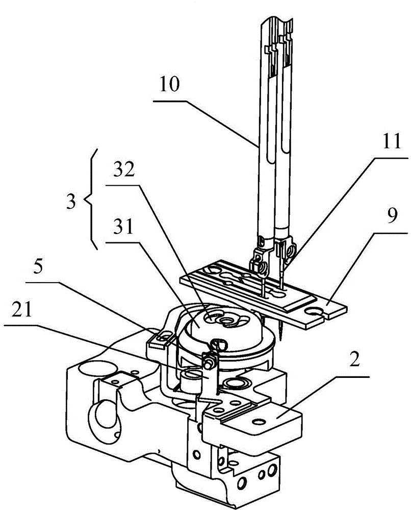
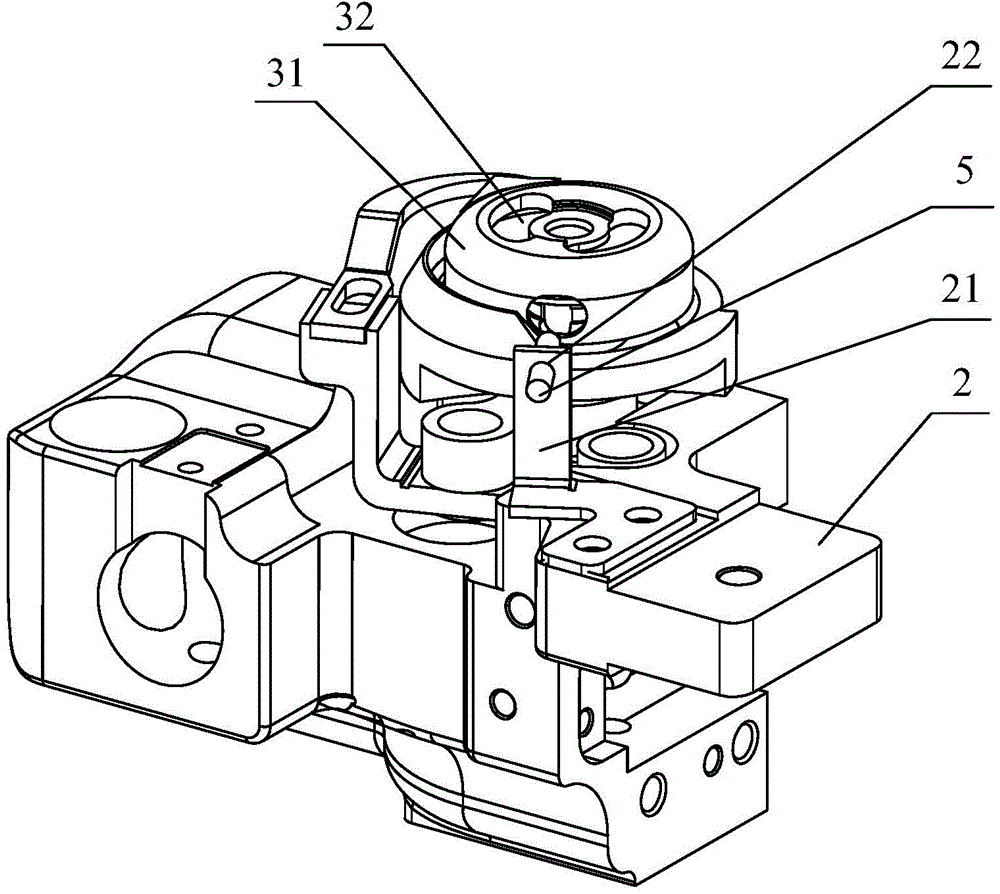
The invention provides a bottom wire detection control system based on an optical fiber sensor and applied to an industrial sewing machine. The system comprises an electric control module, a rotating shuttle and a motor. The rotating shuttle comprises a shuttle case and a shuttle core. The shuttle core comprises a winding post and flanges arranged at the two ends of the winding post. A reflective sheet is fixed to the outer circumferential face of the winding post, and bottom wires are wound around the winding post. The optical fiber sensor is fixed to a shuttle support. The shuttle case is provided with an optical fiber emitter inlet and a gap, wherein the optical fiber emitter inlet and the gap are communicated with each other. The optical fiber sensor is connected with the electric control module through a signal conditioning control circuit. The electric control module is also connected with the motor through an output circuit. The bottom wire detection control system applied to the industrial sewing machine can judge whether the shuttle core is not installed in the shuttle case and whether the bottom wires on the shuttle core are enough according to optical signals of reflected light detected by the optical fiber sensor; meanwhile, the optical fiber sensor is adopted as a detection element, so that the system is high in sensitivity, higher and more reliable in detection performance and higher in anti-electromagnetic-interference capability.

Description

technical field [0001] The invention relates to a sewing machine bobbin thread detection technology, in particular to an optical fiber sensor-based bobbin thread detection and control system and method for industrial sewing machines. Background technique [0002] A sewing machine is a machine that uses one or more sewing threads to form one or more stitches on the sewing material to interweave or sew one or more layers of sewing material. The sewing machine can sew fabrics such as cotton, fiber crops, silk, wool, and artificial fibers, and products such as leather, plastics, and paper. Sewing machines are divided into household sewing machines and industrial sewing machines. Among them, industrial sewing machines are mostly general-purpose sewing machines, including lockstitch sewing machines, chain sewing machines, quilting machines, overlock sewing machines and interlock sewing machines. [0003] When the sewing machine is sewing the fabric, the rotary hook and the needle...

Claims


Application Information

Patent Timeline
Patent Type & Authority Applications(China)
IPC IPC(8): D05B59/00D05B59/02D05B57/14D05B57/26
CPCD05B57/14D05B57/26D05B59/00D05B59/02D05D2305/32
Inventor 许晓红张传有李丽叶彬黄发军
Owner BULLMER ELECTROMECHANICAL TECH
Learn More