Electrostatic chuck and plasma processing equipment

A technology of electrostatic chuck and chuck body, which is applied in the direction of circuits, discharge tubes, electrical components, etc., can solve the problems of increased heat loss of heating element 16, uneven temperature of chuck body 110, and reduced heating efficiency of electrostatic chuck. Achieve the effects of reducing heat loss, improving heating efficiency and heating uniformity, and ensuring sealing performance

Active Publication Date: 2015-02-25
BEIJING NAURA MICROELECTRONICS EQUIP CO LTD
View PDF4 Cites 11 Cited by
  • Summary
  • Abstract
  • Description
  • Claims
  • Application Information

AI Technical Summary

Problems solved by technology

[0010] Since the expansion joint 140 cannot support the chuck body 110 alone, the chuck body 110 must be supported by the insulating ring 154. However, since a part of the heat generated by the heating element 116 will be conducted to the insulating ring 154, the heat loss of the heating element 16 will increase. thus reducing the heating efficiency of the electrostatic c

Method used


Image

  • Electrostatic chuck and plasma processing equipment
  • Electrostatic chuck and plasma processing equipment
  • Electrostatic chuck and plasma processing equipment

Examples


Example Embodiment

[0035] In order for those skilled in the art to better understand the technical solutions of the present invention, the electrostatic chuck and plasma processing equipment provided by the present invention will be described in detail below with reference to the accompanying drawings.
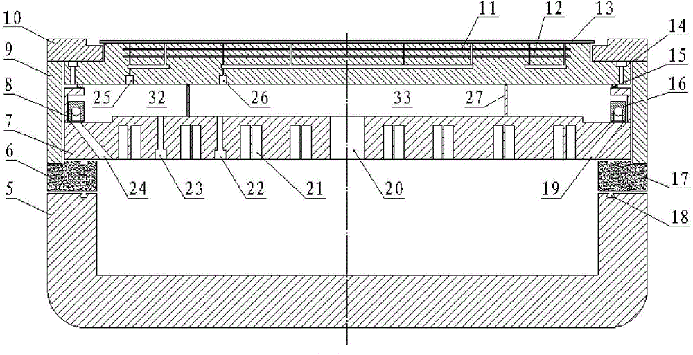
[0036] Figure 3A It is a cross-sectional view of an electrostatic chuck provided in an embodiment of the present invention. Figure 3B for Figure 3A A partial enlarged view of the electrostatic chuck in the middle. Please also refer to Figure 3A and Figure 3B , the electrostatic chuck includes a chuck for carrying the workpiece 13 to be processed, a base 5 , a cooling plate 7 and a heat insulation assembly 8 . The chuck includes a chuck body 14 , an electrostatic electrode 11 and a heating unit 12 arranged in the chuck body 14 . The electrostatic electrode 11 is connected to a DC power supply (not shown in the figure), and the DC power supply provides energy to the electrostatic electro...


PUM


Abstract

The invention provides an electrostatic chuck and plasma processing equipment. The electrostatic chuck comprises a chuck used for bearing a processed workpiece and a base, the chuck comprises a chuck body, an electrostatic electrode arranged in the chuck body and a heating unit, and the electrostatic electrode is connected with a direct-current power source and used for fixing the processed workpiece to the chuck in an electrostatic attraction mode. The heating unit is used for heating the processed workpiece. The base is arranged below the chuck body and used for supporting and fixing the chuck body. A heat insulation assembly is arranged between the chuck body and the base and comprises an expansion heat insulation ring and a cooling unit, the expansion heat insulation ring is a closed thin-wall structural member, and the upper end and the lower end of the expansion heat insulation ring are in sealing contact with the chuck body and the base. The cooling unit is used for cooling the expansion heat insulation ring. The electrostatic chuck can thoroughly solve the heat insulation problem of the chuck, and therefore the heating efficiency and heating uniformity of the electrostatic chuck can be improved.

Description

technical field [0001] The invention relates to the field of semiconductor equipment manufacturing, in particular to an electrostatic chuck and plasma processing equipment. Background technique [0002] In the process of manufacturing integrated circuits (IC) and microelectromechanical systems (MEMS), especially in the process of implementing plasma etching (ETCH), physical vapor deposition (PVD), chemical vapor deposition (CVD), etc., often Electrostatic chucks are used to fix, support and heat processed workpieces such as wafers, provide DC bias voltage for wafers and control the temperature of the wafer surface. [0003] figure 1 It is a schematic diagram of the structure of a typical electrostatic chuck. Such as figure 1 As shown, the electrostatic chuck includes an insulating layer 1 , a heater 2 and an aluminum base 3 stacked in sequence from top to bottom. Among them, the insulating layer 1 adopts AL 2 o 3 or ALN and other ceramic materials, and a DC electrode l...

Claims


Application Information

Patent Timeline
IPC IPC(8): H01L21/683H01L21/67
CPCH01J37/32798H01L21/67011H01L21/6833
Inventor 彭宇霖
Owner BEIJING NAURA MICROELECTRONICS EQUIP CO LTD
Why Eureka
Try Eureka