Light transmission simulation system and simulation method based on carbon nanotube photodetector

A technology of photodetectors and carbon nanotubes, applied in line-of-sight transmission, free space transmission, instruments, etc., can solve problems such as difficult to guarantee accuracy, limited simulation distance, and gap in simulation results, and achieve simple overall structure, short response time, The effect of wide response band

Inactive Publication Date: 2016-09-28
PEKING UNIV
View PDF5 Cites 0 Cited by
  • Summary
  • Abstract
  • Description
  • Claims
  • Application Information

AI Technical Summary

Problems solved by technology

[0007] To sum up, the existing far-field optical transmission simulation methods have a limited simulation distance, which is difficult to meet actual needs, or although they can simulate long distances, there are problems such as cumbersome debugging of simulation methods, difficulty in ensuring accuracy, and demanding image quality in optical path design.
In addition, the influence of factors such as atmospheric channels, space background light, and satellite platform disturbances have not been considered, and there is a certain gap between the simulation results and the actual situation

Method used


Image

  • Light transmission simulation system and simulation method based on carbon nanotube photodetector
  • Light transmission simulation system and simulation method based on carbon nanotube photodetector
  • Light transmission simulation system and simulation method based on carbon nanotube photodetector

Examples


Embodiment Construction

[0038] The present invention will be further described through the embodiments below in conjunction with the accompanying drawings.

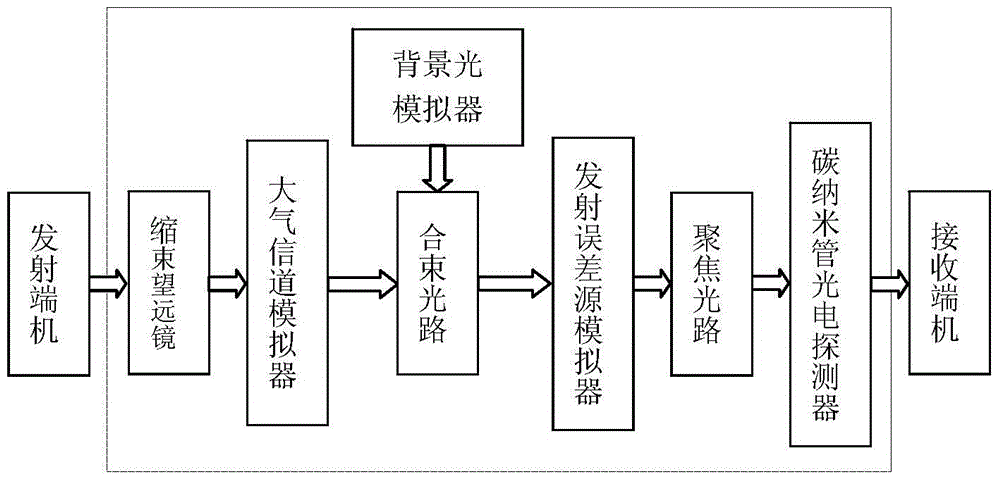
[0039] Such as figure 1 As shown, the optical transmission simulation system based on carbon nanotube photodetectors of the present invention includes: beam shrinking telescope, atmospheric channel simulator, background light simulator, beam combining optical path 4, emission error source simulator 5, focusing optical path 6 and Carbon nanotube photodetector 7; among them, the equivalent Fourier transform lens composed of the shrinking telescope and the focusing optical path; the transmitting end machine emits a parallel beam, enters the shrinking telescope to shrink the beam, and obtains a narrow aperture parallel beam; parallel After the beam passes through the atmospheric channel simulator, the intensity and phase change, and then combines with the background light emitted by the background light simulator through the beam combining optical p...


PUM


Abstract

The invention discloses a carbon nano tube photoelectric detector based light transmission simulation system and a simulation method thereof. The light transmission simulation system comprises a beam reducing telescope, an atmosphere channel simulator, a background light simulator, a beam combining light path, a transmitting error source simulator, a focusing light path and a carbon nano tube photoelectric detector, wherein the beam reducing telescope and the focusing light path form an equivalent Fourier transform lens, and the carbon nano tube photoelectric detector is arranged at the position of a focal plane to perform wave surface sampling so as to obtain incident beam far-field distribution. The distance simulation capacity of the carbon nano tube photoelectric detector based light transmission simulation system is improved by two orders of magnitudes compared with a traditional micro-pore-adopting simulation method. The influence of atmosphere channels, vibration of a satellite platform, background light, orbit errors and other multiple factors is considered, and a situated state is close to the situation that a laser space communication end machine is in orbit. Current signals can be directly obtained, and the photovoltaic conversion link in a traditional simulation method is omitted. The carbon nano tube photoelectric detector based light transmission simulation system is wide in response wave band, short in response time, simple in whole structure and meanwhile high in accuracy.

Description

technical field [0001] The invention relates to the field of space laser communication, in particular to a light transmission simulation system based on a carbon nanotube photodetector and a simulation method thereof. Background technique [0002] As a payload of a satellite, the space laser communication terminal must undergo rigorous testing on the ground for its main technical indicators and performance parameters, whether after the development is completed or before launch, such as tracking and aiming accuracy, Capture characteristics, communication bit error rate, etc. The communication terminal is divided into a transmitting terminal and a receiving terminal, and the two together form a mutually coupled system, that is, a space laser communication system. The test of space laser communication system can be divided into system level, terminal level, sub-system level and module level. Typical ground verification and testing systems at home and abroad include: ESA’s gro...

Claims


Application Information

Patent Timeline
Patent Type & Authority Patents(China)
IPC IPC(8): H04B10/112G02B27/00
Inventor 王建民
Owner PEKING UNIV
Why Eureka
Try Eureka