Ultrasonic wave stirrer

An ultrasonic and agitator technology, applied in the field of ultrasonic agitator, can solve the problems of increasing the frequency and speed of material molecular motion, increasing the penetrating power of solvents, and waste of resources, etc., to achieve enhanced mixing effects, reduced equipment models, and fast fusion speed Effect

Active Publication Date: 2015-03-04
HENAN HENGRUIYUAN IND
View PDF7 Cites 5 Cited by
  • Summary
  • Abstract
  • Description
  • Claims
  • Application Information

AI Technical Summary

Problems solved by technology

[0004] Ultrasonic extraction is to use the strong cavitation effect, mechanical vibration, disturbance effect, high acceleration, emulsification, diffusion, crushing and stirring effects produced by the above-mentioned ultrasonic radiation pressure to increase the frequency and speed of material molecular motion, increase the Solvent penetration, so as to accelerate the target components into the solvent, and promote the extraction process. At present, ultrasonic extraction technology has been used to extract natural products from Eucommia ulmoides to make products such as eucommia rubber. In the extraction technology, ultrasonic agitator is an important part of the extraction process. Equipment, the ultrasonic mixers currently on the market generally have the following disadvantages: 1. The extract and the solution cannot be fully mixed evenly; 2. The size of the mixing tank is fixed and the volume is the same. If the output requirements are different, it is necessary to be equipped with different types of mixer 3. During the extraction process, the vibration of the mixing tank affects the ultrasonic extraction process, resulting in insufficient extraction and low efficiency; 4. The function is single and can only be used for a single ultrasonic extraction, and cannot be used as a single ultrasonic extraction at the same time. common stirring device

Method used


Image

  • Ultrasonic wave stirrer
  • Ultrasonic wave stirrer
  • Ultrasonic wave stirrer

Examples


Embodiment Construction

[0017] The embodiments of the present invention will be described in detail below in conjunction with the accompanying drawings. This embodiment is based on the technical solution of the present invention, and provides detailed implementation methods and specific operating procedures, but the scope of protection of the present invention is not limited to the following embodiments. .

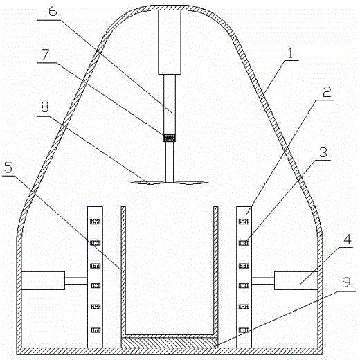
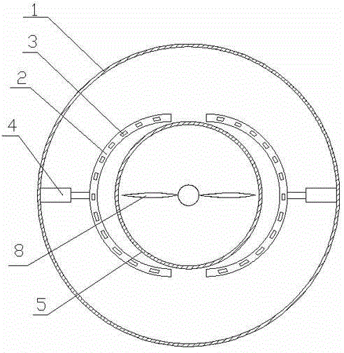
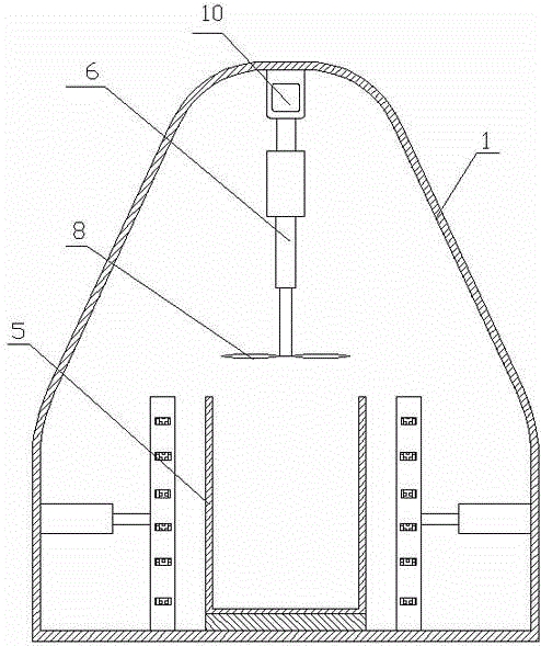
[0018] Such as figure 1 As shown, an ultrasonic mixer includes a housing 1 and a mixing bucket 5 provided inside the housing 1. The mixing bucket 5 is arranged on a circular positioning piece 9 located on the inner bottom of the housing 1. The radius of the positioning piece 9 is The same as the radius of the mixing bucket 5, the positioning piece 9 positions the mixing bucket 5 so that it and the mixing bucket 5 become an integral structure, and also includes an ultrasonic generating mechanism for wrapping the outer wall of the mixing bucket 5, and the ultrasonic generating mechanism includes tw...


PUM


Abstract

The invention discloses an ultrasonic wave stirrer which comprises a shell, a stirring barrel and an ultrasonic wave generation mechanism, wherein ultrasonic wave vibrators are arranged in the ultrasonic wave generation mechanism; the ultrasonic wave generation mechanism can be used for transmitting ultrasonic waves into the stirring barrel and can be also used as a clamping mechanism for the stirring barrel; the ultrasonic wave stirrer is also provided with a stirring device with expansion devices; the stirring device is used for enabling a stirring wheel in a rotating state to do up-and-down reciprocating motion in the stirring barrel to uniformly mix raw materials. According to the ultrasonic wave stirrer, extracts and a solution are fully combined; the ultrasonic wave generation mechanism capable of doing expansion motion can be used for transmitting the ultrasonic waves to the stirring barrels with different sizes, so that the types of equipment are reduced and the cost is lowered; the stirring barrel can be fixed and locked; in an extracting process, the ultrasonic wave generation mechanism can be used for avoiding the phenomenon that ultrasonic wave extraction is affected by vibration of the stirring barrel, so that extraction is complete, and the efficiency is improved; the ultrasonic waves act on the periphery of the stirring barrel, so that the extracts are high in combining speed, and the mixing effect is enhanced.

Description

technical field [0001] The invention relates to the field of biomechanics, in particular to an ultrasonic stirrer used in an ultrasonic extraction process. Background technique [0002] Ultrasound is a sound wave with a frequency higher than 20,000 Hz. It has good directionality, strong penetrating ability, and is easy to obtain concentrated sound energy. It can travel far in water and can be used for distance measurement, speed measurement, cleaning, welding, gravel, and sterilization. Wait. [0003] When the ultrasonic waves propagate in the liquid, due to the violent vibration of the liquid particles, small cavities will be generated inside the liquid. The rapid expansion and closure of these small cavities will cause violent collisions between the liquid particles, resulting in a pressure of thousands to tens of thousands of atmospheres. The violent interaction between the particles will cause the temperature of the liquid to rise suddenly, which plays a very good stir...

Claims


Application Information

Patent Timeline
IPC IPC(8): B01F11/02B01D11/02
Inventor 李银环张学俊张萌萌苏晓兰宋通通
Owner HENAN HENGRUIYUAN IND
Why Eureka
Try Eureka