
Removed material collecting and dust removing system during drilling process of carbon fiber composite material

A composite material, dust removal system technology, applied in the direction of removing smoke and dust, dispersing particle filtration, metal processing, etc., can solve problems such as destructive influence of machine tool equipment and operators

Inactive Publication Date: 2015-03-04
HARBIN UNIV OF SCI & TECH
View PDF5 Cites 5 Cited by
  • Summary
  • Abstract
  • Description
  • Claims
  • Application Information

AI Technical Summary

Problems solved by technology

[0004] The purpose of the present invention is to solve the problem of the destructive influence of the powder produced by the drilling of carbon fiber composite materials on the quality of the workpiece, the environment, the machine tool equipment and the operator, and propose a material collection and dust removal system for the removal of materials during the drilling process of carbon fiber composite materials

Method used


Image

  • Removed material collecting and dust removing system during drilling process of carbon fiber composite material
  • Removed material collecting and dust removing system during drilling process of carbon fiber composite material
  • Removed material collecting and dust removing system during drilling process of carbon fiber composite material

Examples


Embodiment Construction

[0018] The present invention will be further described in detail below in conjunction with the accompanying drawings.

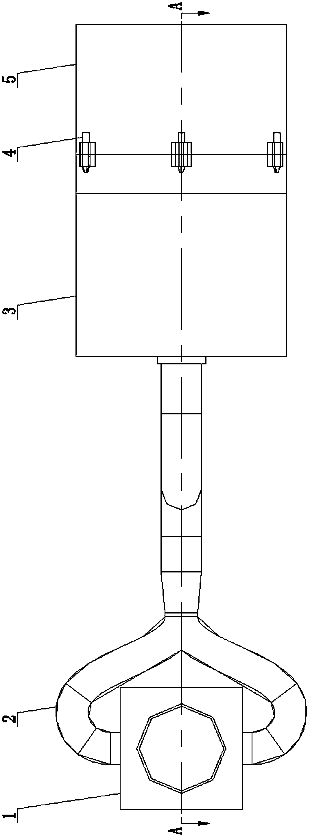
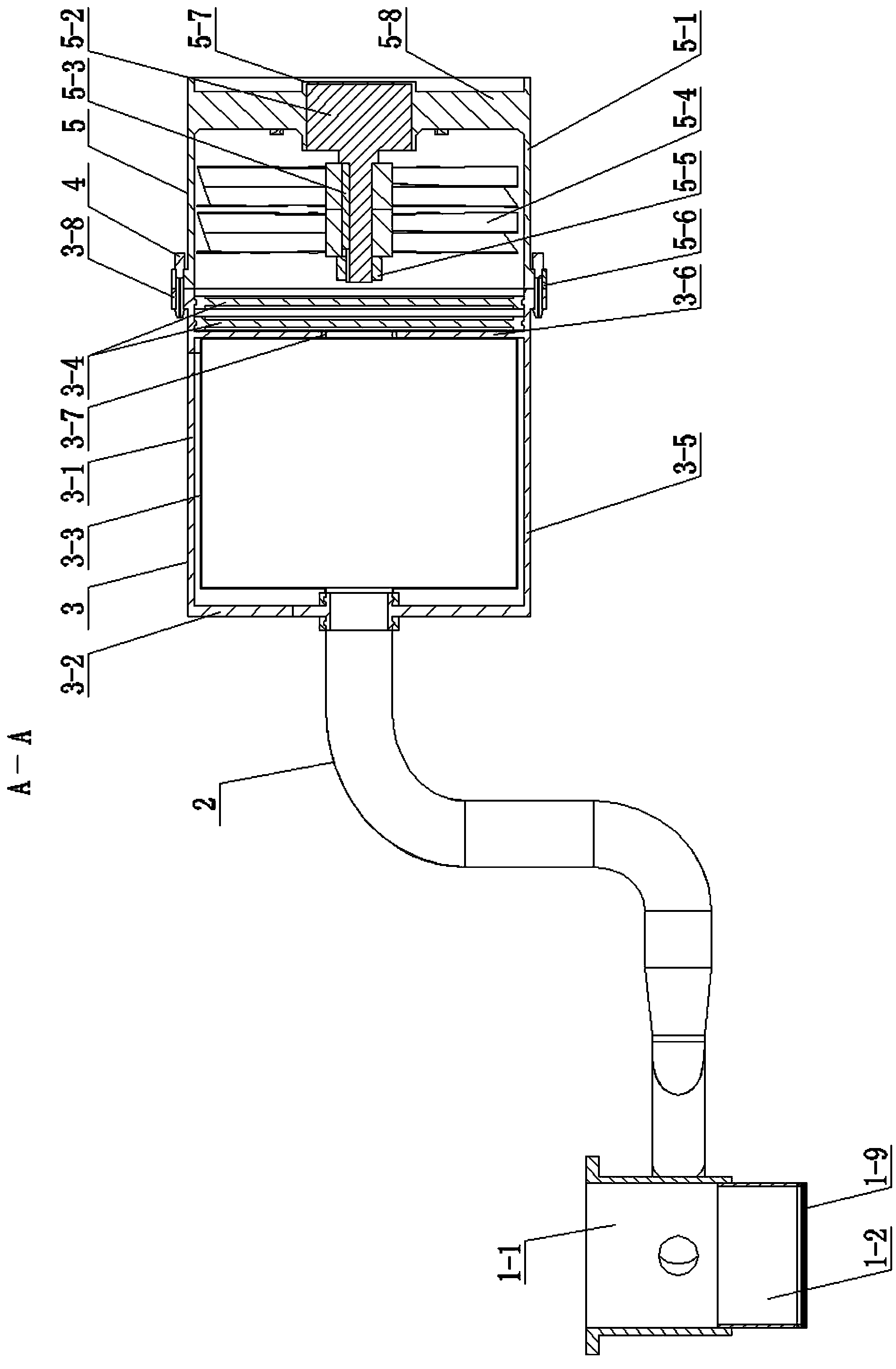
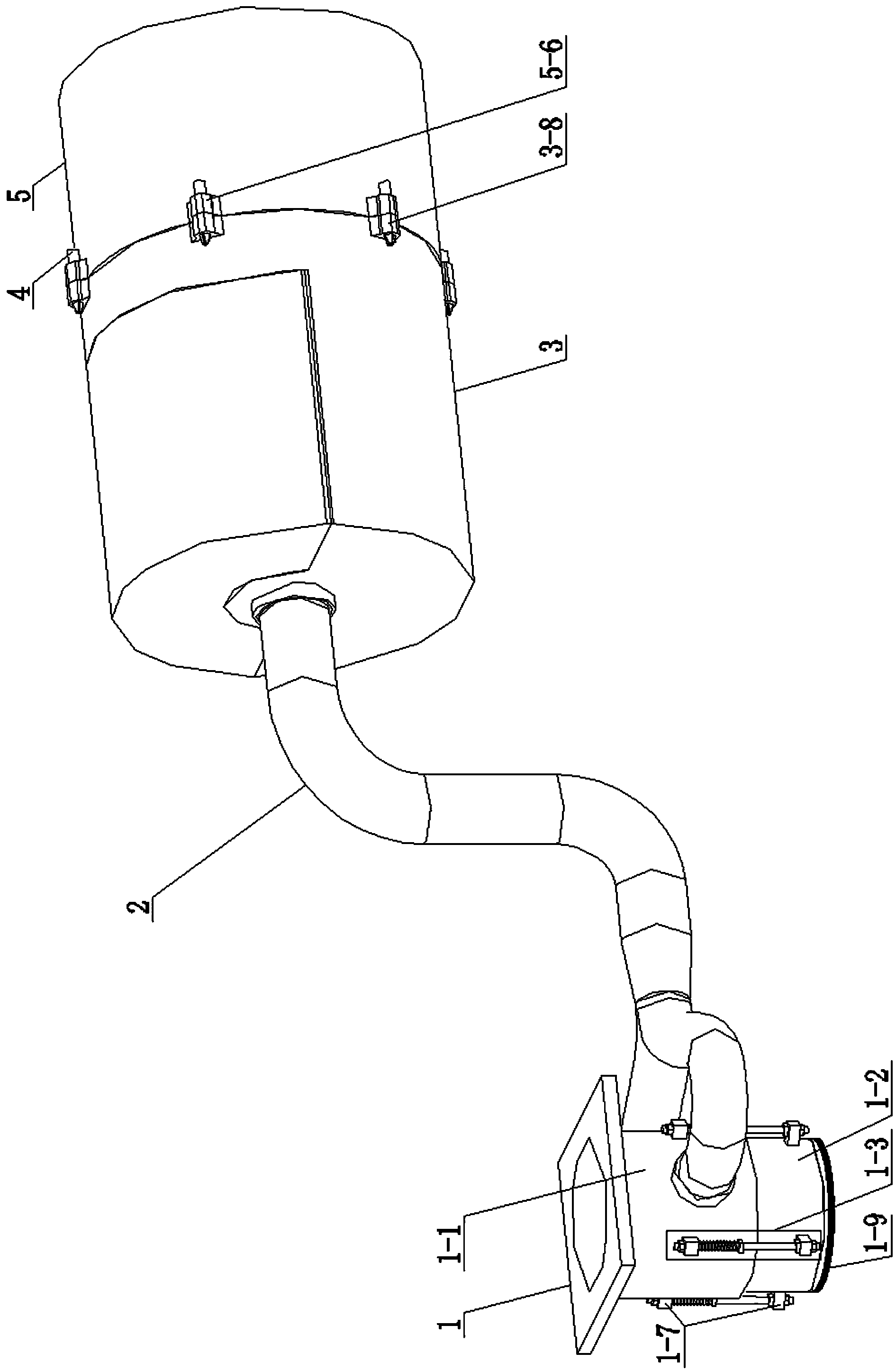
[0019] Such as Figure 1~Figure 9 As shown, the removal material collection and dust removal system during the carbon fiber composite material drilling process includes a retractable dust collection device 1 in the feed direction, an intake manifold 2, a removal material collection and dust removal device 3, a turbofan fan device 5 and multiple Self-locking cotter pin 4; one end of the collection and dust removal housing 3-1 of the removal material collection and dust removal device 3 is a closed end, and the other end is an open end; the fan housing 5-1 of the turbofan fan device 5 Both ends are open ends; the air inlet of the intake manifold 2 is fixedly connected to the side wall of the main shaft connecting sleeve 1-1 of the retractable dust collection device 1 in the feeding direction and is connected to the main shaft. The inner cavity of the sleeve 1-...


PUM


Abstract

The invention discloses a removed material collecting and dust removing system during a drilling process of a carbon fiber composite material, belongs to the technical field of machining an engineering composite material and aims to solve the problem of a frustrating effect which is generated on workpiece quality, environment, machine tool equipment and operators due to powder generated by drilling of the carbon fiber composite material. The removed material collecting and dust removing system is characterized in that an air inlet of an air inlet manifold is fixedly connected with the side wall of a main shaft connecting sleeve of a telescopic dust removing device in the feeding direction and is communicated with an inner cavity of the main shaft connecting sleeve, and an air outlet of the air inlet manifold is fixedly connected with the closed end of a collecting and dust removing shell of a removed material collecting and dust removing device and is communicated with an inner cavity of the collecting and dust removing shell of the removed material collecting and dust removing device; the collecting and dust removing shell of the removed material collecting and dust removing device is connected with a draught fan shell of a turbofan draught fan device through multiple self-locking opening pins. The removed material collecting and dust removing system disclosed by the invention is used for carrying out collecting and dust removing during the drilling process of the carbon fiber composite material, and the frustrating effect which is generated on the workpiece quality, the environment, the machine tool equipment and the operators can be effectively avoided.

Description

technical field [0001] The invention relates to a material collection and dust removal system for carbon fiber composite material processing, which belongs to the technical field of engineering composite material processing. Background technique [0002] Carbon fiber composite materials have excellent properties such as high modulus, smaller mass than aluminum, greater strength than steel, corrosion resistance, fatigue resistance, etc., and have been widely used in military and civilian aerospace, automobile, machinery, chemical and other fields. Structural and functional materials. It plays an important role in military equipment such as rockets, satellites, and fighter planes, as well as large civilian aircraft, wind power equipment, nuclear power equipment, and high-end auto parts. The application of carbon fiber composite parts has significantly improved the structural strength and life of the equipment, and reduced the weight, which has also played a very important rol...

Claims


Application Information

Patent Timeline
Patent Type & Authority Applications(China)
IPC IPC(8): B26D7/18B08B15/04B01D46/02B01D46/10
Inventor 刘利吴明阳程耀楠田勇王彤
Owner HARBIN UNIV OF SCI & TECH
Learn More