Method for judging gas fleeing time

A technology of gas escape and time, which is applied in the direction of mining fluid, earthwork drilling, measurement, etc., can solve the problems affecting the time of gas escape, gas production speed fluctuations, irregular changes, etc., to avoid inaccuracy, reduce interference, The effect of good technical applicability

Active Publication Date: 2015-03-04
CHINA UNIV OF PETROLEUM (BEIJING)
View PDF3 Cites 8 Cited by
  • Summary
  • Abstract
  • Description
  • Claims
  • Application Information

AI Technical Summary

Problems solved by technology

[0003] In research CO 2 When determining the gas channeling time during the oil displacement process, an important content is to determine the gas channeling time, but the existing research does not have a clear method to define the gas channeling time, including laboratory experiments and field gas injection tests, for There is no clear way to determine when to define gas channeling after seeing gas
[0004] At present, the judgment of gas channeling is generally based on the stable gas production rate, a large increase in the gas-oil ratio produced, or the change rate of the mole fraction of the characteristic components. However, these methods have limitations as the evaluation methods of gas channeling.
For example, when the gas channeling time is defined by a single significant increase in the gas-oil ratio produced, the gas-oil ratio changes in a large and irregular range because the gas channeling channel has just begun to form, and is affected by the interference of some special points on the definition of gas channeling , resulting in the inability to accurately determine the gas channeling time point
For example, when the mole fraction change rate of characteristic components is used to define the gas channeling time, it is greatly affected by the components of the produced gas and crude oil, and the mole fraction change rate fluctuates greatly before and after gas channeling, which affects the judgment of gas channeling time
This is because before and after the gas channeling, the gas production rate and gas-oil ratio also fluctuate greatly, and only when the gas channeling channels are fully formed, the changes of the two tend to be stable, but at this time it is impossible to determine the time point when the gas channeling begins
Therefore, from a technical point of view, the above method to determine the time point of gas channeling can be used as a reference factor for determining gas channeling, but it is not universally applicable

Method used


Image

  • Method for judging gas fleeing time
  • Method for judging gas fleeing time
  • Method for judging gas fleeing time

Examples


Embodiment 1

[0038] This embodiment provides a method for determining the gas escape time, wherein, the present embodiment adopts a natural outcrop sandstone core model, the core size is 30cm×4.5cm×4.5cm, the porosity is 22%, and the permeability is 1.7×10 -3 μm 2 ; The water used is oil well produced water, and the water type is CaCl 2 type, the salinity is 80.06g / L; the crude oil used is oilfield crude oil, the density of degassed crude oil is 0.8579g / mL, and the surface viscosity is 11.54mPa·s. Crude oil, the simulated crude oil viscosity is 4.87mPa s (45°C); CO 2 The purity of the gas is 99.99%, and the experimental temperature is 45°C.

[0039] The method for determining gas blow-by time provided in this embodiment includes the following steps:

[0040] Put the core in the core holder, check the tightness of the system, vacuumize the system, and then use pressurization to fully saturate the water produced by the oil wells in the oil field to obtain a water-saturated core with a rec...

Embodiment 2

[0049] This embodiment provides a method for determining the gas escape time, wherein, the present embodiment adopts a natural outcrop sandstone core model, the core size is 30cm×4.5cm×4.5cm, the porosity is 23%, and the permeability is 2.5×10 -3 μm 2 , the water used is oil well produced water, and the water type is CaCl 2 type, the salinity is 80.06g / L; the crude oil used is oilfield crude oil, the density of degassed crude oil is 0.8579g / mL, and the surface viscosity is 11.54mPa·s. Crude oil, the simulated crude oil viscosity is 4.87mPa s (45°C); CO 2 The purity of the gas is 99.99%; the experimental temperature is 45°C.

[0050] The method for determining gas blow-by time provided in this embodiment includes the following steps:

[0051] Put the core in the core holder, check the tightness of the system, vacuumize the system, and then use pressurization to fully saturate the water produced by the oil well in the oil field to obtain a water-saturated core with a recorded...

Embodiment 3

[0060] This example provides a method for determining the gas escape time, which is based on the low-permeability injection of CO in a domestic oilfield. 2 Take the pilot mine as an example. The mine includes multiple oil production wells. The implementation targets are 1# oil production well and 2# oil production well. Among them, the average liquid production of 1# oil production well is 9.1t / d, and the water content is 2.06 %.

[0061] The method for judging the gas channeling time of the 1# production well provided in this embodiment includes the following steps:

[0062] CO2 was carried out on the 1# production well 2 Gas displacement at constant pressure to obtain oil-gas mixture;

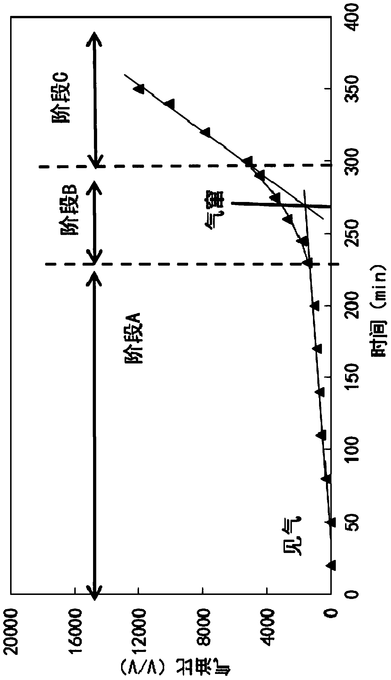
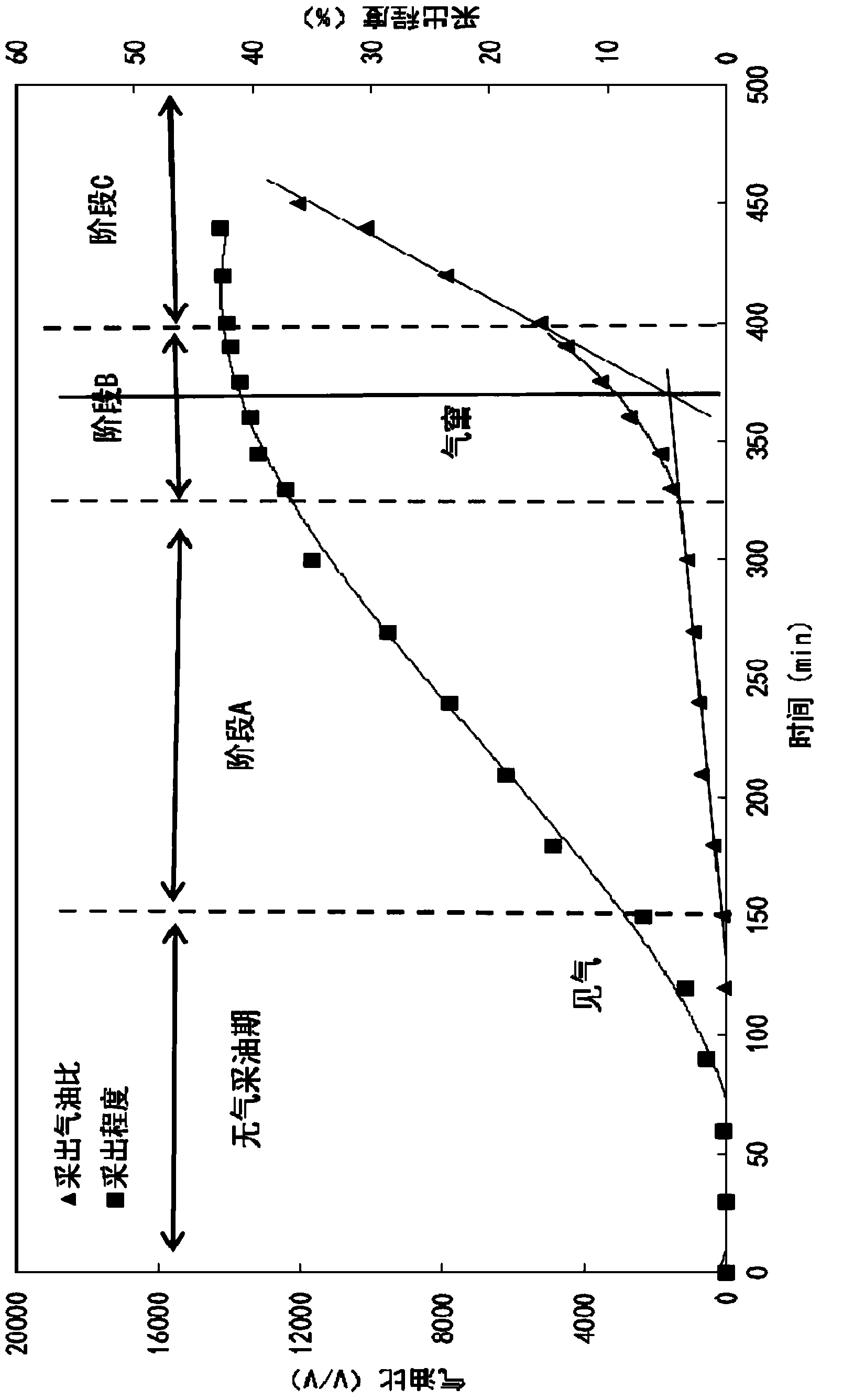
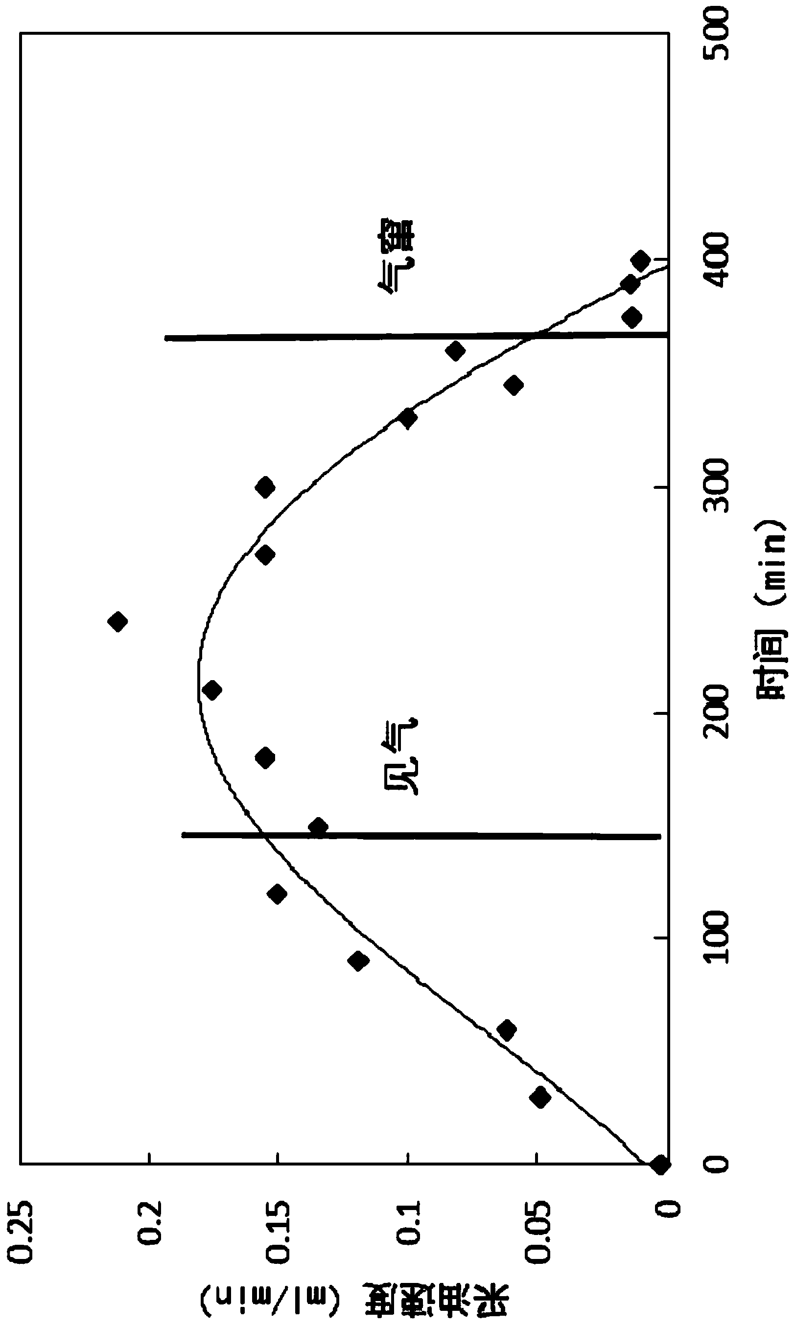
[0063] As the displacement progresses, the oil-gas mixture is separated, the oil output and gas output at each time point are measured, and the gas-oil ratio at each time point is obtained; the gas-oil ratio varies with the injection time. Figure 5 As shown, according to the change trend ...


PUM

PropertyMeasurementUnit
Permeabilityaaaaaaaaaa
Salinityaaaaaaaaaa
Core permeabilityaaaaaaaaaa

Abstract

The invention provides a method for judging gas fleeing time. The method comprises the steps that a change curve of an oilfield produced gas-oil ratio along with injection time is built; according to the change rate of the gas-oil ratio, the change curve of the oil field produced gas-oil ratio along with the injection time is divided into a primary gas appearing stage, a gas fleeing channel primary forming stage and a complete gas fleeing stage which are marked as the stage A, the stage B and the stage C respectively; the linear trend lines of change curve bodies of the oilfield produced gas-oil ratio along with the injection time in the stage A and the stage C are respectively built, and the cross point of the two linear trend lines is taken as the gas fleeing time. The method for judging the gas fleeing time can accurately judge the gas fleeing time.

Description

technical field [0001] The invention relates to a method for judging the gas escape time, which belongs to the technical field of petroleum exploitation. Background technique [0002] In recent years, with the continuous increase of crude oil demand, the technology of enhanced oil recovery has developed rapidly, and the technology of gas injection enhanced oil recovery has become one of the most attractive oil displacement technologies in tertiary oil recovery. CO injection in Daqing, Shengli, Jilin and Yanchang oilfields 2 Oil flooding deposit tests all show that CO 2 Oil flooding is one of the effective methods to develop low-permeability reservoirs in my country. However, due to the heterogeneity of the reservoir and the unfavorable mobility ratio of the injected gas, during the gas injection development process, the gas often breaks through prematurely, forming gas channeling, and the injected gas often follows the formation fractures or high Channeling of seepage cha...

Claims


Application Information

Patent Timeline
IPC IPC(8): E21B43/22E21B47/00E21B49/00G06F19/00
CPCE21B43/164E21B47/00E21B49/00G16Z99/00
Inventor 侯吉瑞端祥刚赵凤兰马云飞张宗勋王潇
Owner CHINA UNIV OF PETROLEUM (BEIJING)
Why Eureka
Try Eureka