Cement bin and manufacturing process thereof

A cement silo and cone technology, applied in the field of machinery, can solve the problems of long production cycle of the silo, waste of solder resources, harsh working environment, etc., to achieve the improvement of processing accuracy and product quality and aesthetics, shorten the production cycle, realize normalized effect

Inactive Publication Date: 2015-03-11
潍坊金河机械有限公司
View PDF8 Cites 6 Cited by
  • Summary
  • Abstract
  • Description
  • Claims
  • Application Information

AI Technical Summary

Problems solved by technology

[0002] At present, the cement silos commonly used in the market generally have a capacity of several hundred tons, are relatively large, and need to be welded in sections. They are roughly divided into an upper cone, a middle cylinder, and a lower cone, all of which are assembled by pieces. In the prior art, the flanges are generally welded directly around the silo pieces. This connection method requires a large number of welding workers and solder. Pollution and waste of solder resources. In addition, due to manual welding, there will inevitably be deviations between the silo pieces. After the overall assembly, the gaps are too large and water seepage is easy, there are many welds, and the entire silo is skewed. The silo production cycle of the method is long and the cost is high
If the silo pieces of the upper cone, the middle cylinder and the lower cone are directly welded, the above-mentioned shortcomings will be more prominent

Method used


Image

  • Cement bin and manufacturing process thereof
  • Cement bin and manufacturing process thereof
  • Cement bin and manufacturing process thereof

Examples


Embodiment 1

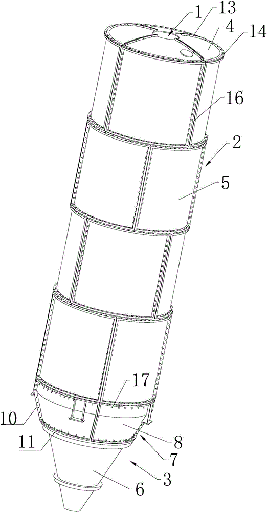
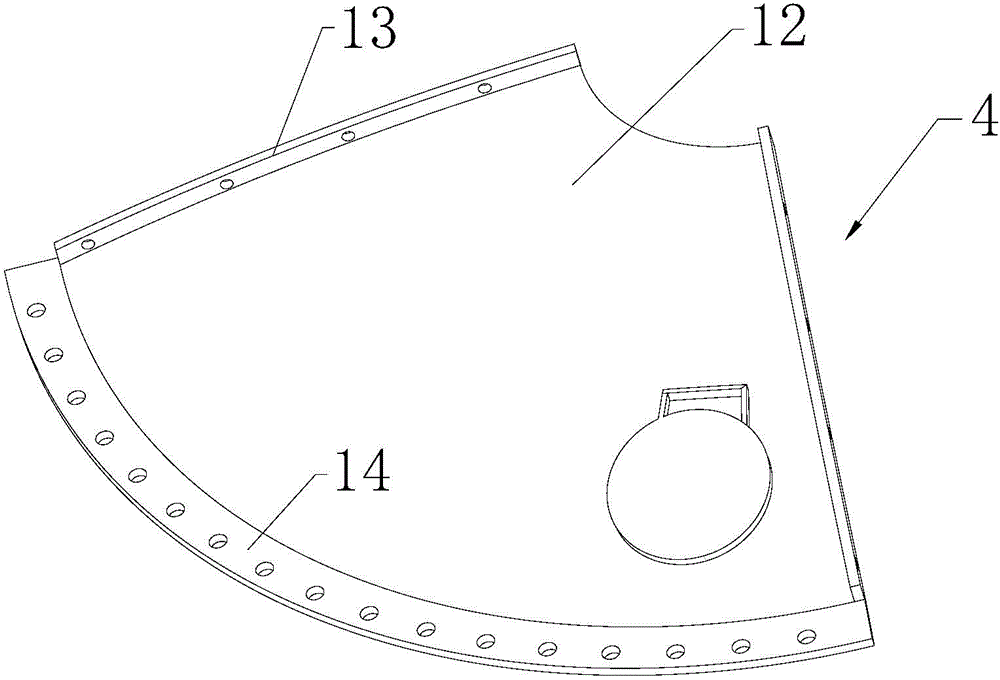
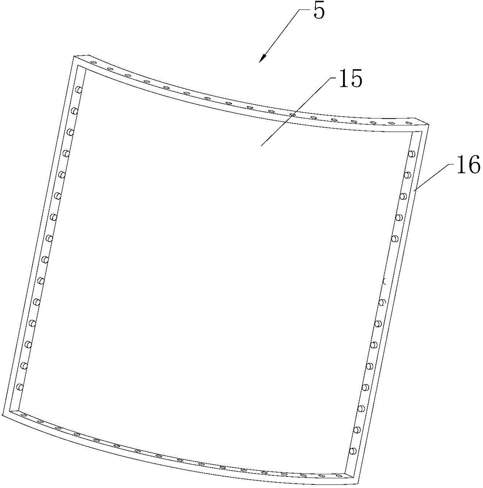
[0026] like figure 1 and Figure 4 Commonly shown, the cement silo, from top to bottom, includes an upper cone 1, a middle cylinder 2 and a lower cone 3 connected by fasteners; the upper cone 1 includes several upper cone splicing modules 4 of the same size , several upper cone splicing modules 4 are assembled to form the upper cone 1; the middle cylinder 2 includes several intermediate cylinder splicing modules 5 of the same size, and several intermediate cylinder splicing modules 5 are assembled to form the middle cylinder 2; the lower cone 3 Including an end cone 6 and at least one conical cylinder 7, the conical cylinder 7 and the end cone 6 are installed together by fasteners, the conical cylinder 7 includes several conical cylinder splicing modules 8, several conical cylinder splicing modules 8 is assembled to form a conical cylinder 7, and each conical cylinder splicing module 8 includes a conical cylinder splicing module body 9, and the left and right sides of the con...

Embodiment 2

[0034] The manufacturing process of the cement silo includes the following steps:

[0035] step one

[0036] Make the upper cone splicing module 4; cut out some trapezoidal metal plates required for making the upper cone splicing module 4 with a numerical control machine tool, and use a drilling mold to carry out the trapezoidal metal plates required for the upper cone splicing module 4 on the left and right sides. Drill holes, then use the upper cone splicing module stamping die to bend the trapezoidal metal sheet into an arc shape through a hydraulic press, and punch out strip flanges on both sides of the metal sheet, and then fix the strip flanges on both sides, The lower end of the metal plate is welded with arc-shaped flanges, and finally the two shaped flanges are loosened, and the manufacture of an upper cone splicing module 4 is completed.

[0037] step two

[0038] Make the intermediate cylinder splicing module 5; cut out a number of rectangular metal plates require...


PUM


Abstract

The invention discloses a cement bin and a production process thereof. The cement bin sequentially comprises an upper cone, a middle barrel and a lower cone; the upper cone is formed by assembling a plurality of upper cone splicing modules; the middle barrel is formed by assembling a plurality of middle barrel splicing modules; the lower cone comprises a tail end cone and at least one cone barrel; the cone barrel comprises a plurality of cone barrel splicing modules; a plurality of cone barrel splicing modules are assembled to form the cone barrel; both left and right sides of each cone barrel splicing module body are respectively provided with cone barrel strip flanges which are integrally formed by a hydraulic press; each two adjacent cone barrel strip flanges are installed together; both upper and lower ends of each cone barrel splicing module body are welded with cone barrel arc flanges fixedly connected with the upper end of the middle barrel. According to the invention, the production period is greatly shortened, cost is greatly reduced, all bin bodies are consistent in size, the cement bin can be produced in batches, standardization is implemented, and the cement bin is convenient to transport and can be rapidly assembled in field.

Description

technical field [0001] The invention relates to the field of machinery, in particular to a cement silo and a manufacturing process thereof. Background technique [0002] At present, the cement silos commonly used in the market generally have a capacity of several hundred tons, are relatively large, and need to be welded in sections. They are roughly divided into an upper cone, a middle cylinder, and a lower cone, all of which are assembled by pieces. In the prior art, the flanges are generally welded directly around the silo pieces. This connection method requires a large number of welding workers and solder. Pollution and waste of solder resources. In addition, due to manual welding, there will inevitably be deviations between the silo pieces. After the overall assembly, the gaps are too large and water seepage is easy, there are many welds, and the entire silo is skewed. The production cycle of the silo in this way is long and the cost is high. If directly welding its ab...

Claims


Application Information

Patent Timeline
Patent Type & Authority Applications(China)
IPC IPC(8): B65D88/26B65D90/08
CPCB65D88/26B65D90/08
Inventor 王永祥
Owner 潍坊金河机械有限公司
Why Eureka
Try Eureka