

Exhaust treatment system
A technology for exhaust gas treatment and exhaust pipe, applied in the direction of exhaust gas treatment, electronic control of exhaust gas treatment device, exhaust device, etc., can solve the problems of increasing harmful substance concentration, increasing fuel consumption rate, increasing mass fraction, etc. Achieve the effect of reducing emission increase, advancing working time, and shortening light-off time
- Summary
- Abstract
- Description
- Claims
- Application Information
AI Technical Summary
Problems solved by technology
Method used
Image

Examples
Embodiment 1
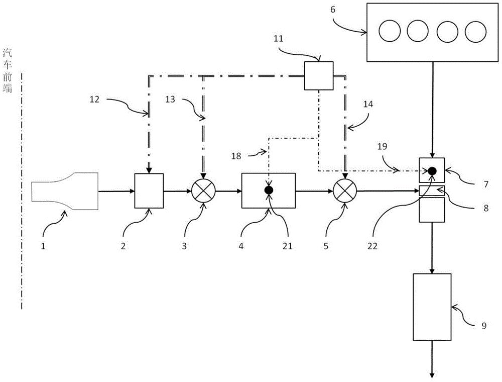
[0028] Such as figure 1 As shown, an exhaust treatment system includes: a compressor 2 , an injector 8 , an exhaust pipe 7 and a controller 11 . The compressor 2 and the injector 8 are connected through pipelines, the exhaust pipe 7 is installed on the injector 8 , and the controller 11 is electrically connected with the compressor 2 through the first control line 12 . The compressor 2 is an electric-driven compressor, and the controller 11 can select PLC, single-chip microcomputer or other logic controllers or control circuits.
[0029] When in use, the exhaust pipe 7 is connected to the engine 6 and the catalytic converter 9 through pipelines, the compressor 2 compresses the air in the environment and pushes it to the injector 8, and the injector 8 sprays the pressurized air into the exhaust pipe 7. This air and the exhaust gas from the engine 6 are mixed in the exhaust pipe 7 and flow to the catalytic converter 9 for redox treatment. The rotational speed of the compressor...
Embodiment 2
[0034] An exhaust treatment system, which is improved on the basis of Embodiment 1, no longer directly connects the compressor 2 and the injector 8, but installs a first valve 3 between the compressor 2 and the injector 8, The first valve 3 is connected with the compressor 2 and the ejector 8 through pipelines, and the first valve 3 is also electrically connected with the controller 11 through a control line, and other structures are the same as those in the first embodiment. The advantage of this design is that the controller 11 can adjust the flow of air by directly regulating the opening degree of the first valve 3 . The first valve 3 adds a controllable point to the whole system, thereby improving the controllability and stability of the exhaust gas treatment system.
Embodiment 3
[0036] Such as figure 1As shown, an exhaust gas treatment system is improved on the basis of the first embodiment, the compressor 2 and the injector 8 are no longer directly connected, but a stabilized pressure is installed between the compressor 2 and the injector 8 The chamber 4 and the plenum chamber 4 are respectively connected to the compressor 2 and the injector 8 through pipelines, and other structures are the same as those in the first embodiment. The function of the plenum chamber 4 is to collect the airflow and stabilize the system pressure. Preferably, a first pressure sensor 21 is disposed in the pressure stabilizing chamber 4 , and the first pressure sensor 21 is electrically connected to the controller 11 through the second detection line 18 . The pressure value in the plenum chamber 4 is obtained by the first pressure sensor 21 and fed back to the controller 11. The controller 11 compares the pressure value of the plenum chamber 4 with the standard value, outpu...
PUM
 Abstract
Description
Claims
Application Information