High-speed heavy-load mute tow chain

A quiet, high-speed technology, applied in the field of towlines, can solve the problems of high noise, high speed and heavy loads of towlines, etc.

Active Publication Date: 2015-03-11
JIANGSU KRIUS MACHINE TOOL ACCESSORIES
View PDF5 Cites 4 Cited by
  • Summary
  • Abstract
  • Description
  • Claims
  • Application Information

AI Technical Summary

Problems solved by technology

[0006] The invention provides a high-speed heavy-duty silent towline, the purpose of which is to overcome the contradiction between the high-speed heavy-duty and silent towline, and solve the technical problem of the high-speed and heavy-duty operating environment of the towline with large noise

Method used


Image

  • High-speed heavy-load mute tow chain
  • High-speed heavy-load mute tow chain
  • High-speed heavy-load mute tow chain

Examples


Embodiment 1

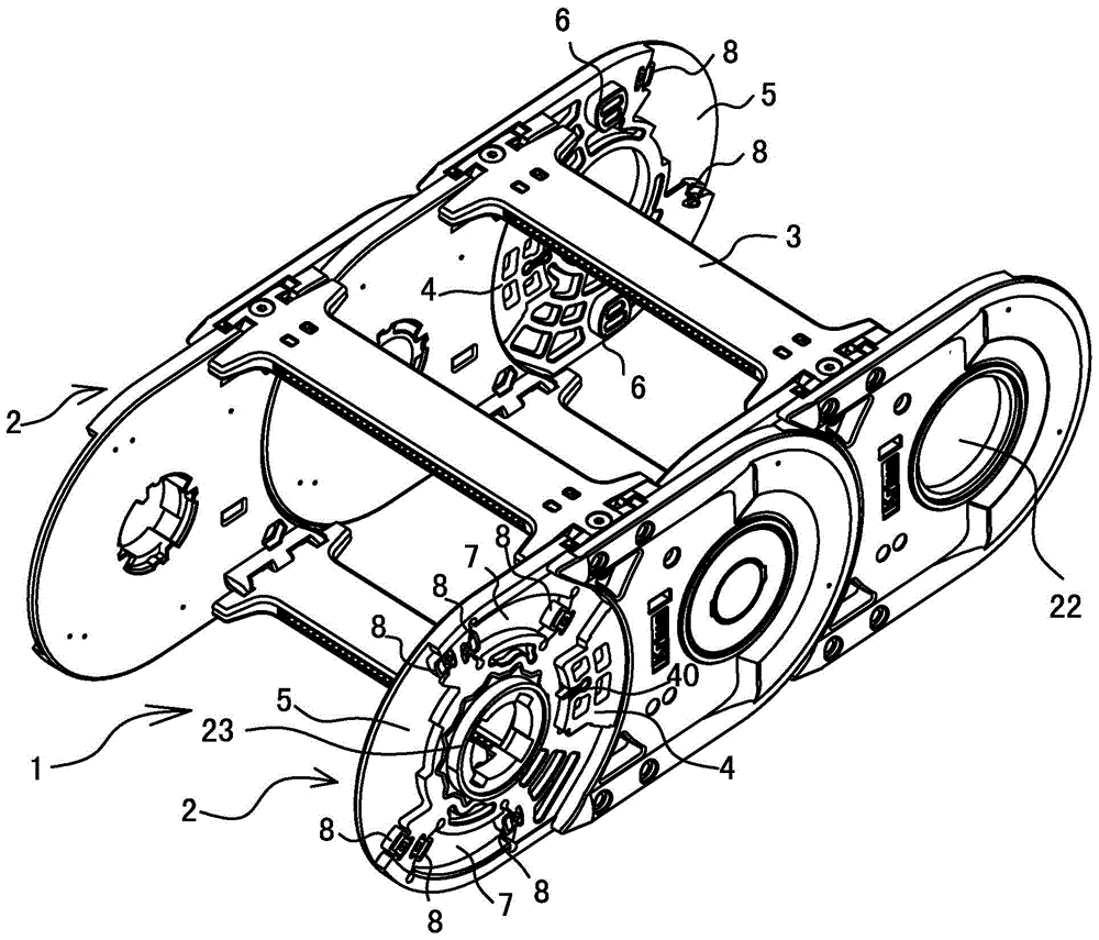
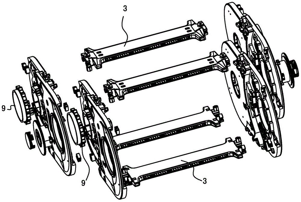
[0069] Embodiment one: see attached Figure 1-2 , attached Figure 5-18 , attached Figure 22 , a high-speed heavy-duty silent drag chain, which is composed of several chain links 1 with the same shape, size and structure connected end to end.

[0070] Wherein, each chain link 1 is composed of two chain plates 2 and a cross bar 3 fixedly connecting the two chain plates 2, the two chain plates 2 in each chain link 1 have the same shape, size and structure, and the chain The center line in the length direction of section 1 is arranged parallel and symmetrically to the datum.

[0071] The cross bar 3 has upper and lower layers. The top or bottom of the chain plate 2 is provided with a positioning groove 20. The positioning part of the cross bar 3 is fixed with the positioning groove 20 of the chain plate 2. In the assembled state, the positioning surface of the cross bar 3 Embed in the positioning groove 20 of the chain plate 2.

[0072] Between any two adjacent chain links 1...

Embodiment 2

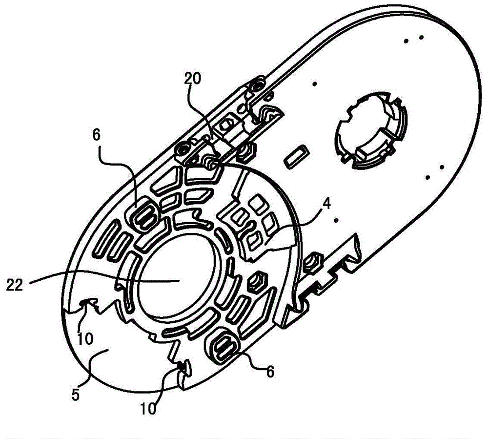
[0092] Embodiment two: see attached Figure 19 , and the rest are the same as in Embodiment 1, except that each column groove structure is formed by a column groove structure located on the inner side and another column groove structure located on the outside arranged side by side in the radial direction of the circumference. That is to say, there is another column groove structure inside the outer column groove structure, and two column groove structures are arranged side by side along the radial direction of the circumference, which can further share the impact force on the chain plate 1 . In this embodiment, there are four post-groove structures and two block-shaped structures. The first post-groove structure is reflected on the chain plate 2 of the previous chain link 1 as a convex post 6, and the second post-groove structure is The structure is reflected in the arc-shaped groove 7 on the chain plate 2 of the previous chain link 1; the third column groove structure is refl...

Embodiment 3

[0094] Embodiment three: see attached Figure 20 As shown, the rest are the same as in Embodiment 1, the difference is that the four rotation limiting structures are composed of four column groove structures, and the rotation limiting structures of the four column groove structures are based on the center of the rotating connection Arranged at intervals in the circumferential direction. In this embodiment, the four rotation limiting structures are column-groove structures. The first column-groove structure is reflected on the chain plate 2 of the previous chain link 1 as a convex column 6, and the second column-groove structure Reflected on the chain plate 2 of the previous chain link 1 is an arc-shaped groove 7; the third column groove structure is reflected on the chain plate 2 of the previous chain link 1 as a convex column 6, and the fourth column groove structure Reflected on the chain plate 2 of the previous chain link 1 is an arc-shaped groove 7 .

[0095] In this emb...


PUM


Abstract

The invention relates to a high-speed heavy-load mute tow chain composed of a plurality of chain links which are connected end to end, wherein a rotary limiting mechanism is arranged at the rotary connection part of every two chain links and is formed by four rotary limiting structures distributed at intervals in the peripheral direction by taking the center of the rotary connection as reference; each rotary limiting structure is composed of a first structure arranged at the tail side surface of a chain plate of the previous chain link and a second structure correspondingly arranged at the head side surface of a chain plate of the next chain link, and the first structures are matched with the second structures; the rotation angles and directions, reflected between every two adjacent chain links, of the four rotary limiting structures are the same, so that load and impact, which are brought by the rotary limiting structures, between the two adjacent chain links can be shared together; in order to realize mute in each rotary limiting structure, a buffer component is arranged between the impact surfaces of the first structure and the second structure at two ends of the corresponding rotary limiting structure. Since a multi-support and multi-buffer structure is adopted, the high-speed heavy-load mute tow chain has the beneficial effects of high speed, heavy load and mute property.

Description

technical field [0001] The invention belongs to the field of towlines, in particular to a functional towline for guiding and protecting flexible objects such as hoses and cables, in particular to a towline suitable for high-speed and heavy-load environments with a mute effect (it can also be used for low speed heavy load or low speed light load environment). Background technique [0002] Drag chain is a kind of functional chain used in reciprocating motion occasions to pull and protect its built-in cables, hoses and other objects. Drag chains are generally used in technical fields such as CNC machine tools, electronic equipment, stone machinery, glass machinery, door and window machinery, injection molding machines, manipulators, lifting and transportation equipment, automated warehouses, and robots. [0003] The drag chain is usually formed by connecting multiple chain links through shafts, each chain link has two chain plates, and each chain plate is provided with two hol...

Claims


Application Information

Patent Timeline
Patent Type & Authority Applications(China)
IPC IPC(8): F16G13/12F16G15/14
CPCF16G13/12F16G15/14F16G13/16
Inventor 李亚庆
Owner JIANGSU KRIUS MACHINE TOOL ACCESSORIES
Why Eureka
Try Eureka