
Laser flash method-based thermal diffusion coefficient test device and method

A technology of thermal diffusivity and testing equipment, applied in the direction of material thermal development, etc., can solve the problems of hydraulic and thermal inlet length evaluation errors, large errors, and inability to obtain isotropic molten salt

Inactive Publication Date: 2015-03-11
SHANGHAI INST OF APPLIED PHYSICS - CHINESE ACAD OF SCI
View PDF6 Cites 13 Cited by
  • Summary
  • Abstract
  • Description
  • Claims
  • Application Information

AI Technical Summary

Problems solved by technology

For example, although the hot wire method mentioned above is simple and convenient, the error caused by the severe shunt phenomenon caused by the conductivity of the molten salt increases with the temperature is 20%; the hot plate method can reduce the ionization degree of the molten salt, However, there are few available container materials and the design is complicated; the radiative heat loss of the periodic heat flow method is small, but the evaluation of hydraulics and the length of the thermal inlet brings errors, and the error is 20%.
In the 1960s, the Oak Ridge National Laboratory of the United States proposed a variable gap method aimed at measuring the thermal conductivity of molten salt, but actual thermal calculations show that the error of this method is larger, and the experimental error can reach 400%.
[0005] However, for the laser flash method, the inhomogeneity of the sample itself will cause large errors
Since the density of molten salt decreases with the increase of temperature, it is impossible to obtain isotropic molten salt by directly setting the molten salt in the existing sample dish and using the existing laser flash method for testing, and it is also impossible to obtain accurate test results
Therefore, the test method of molten salt thermal diffusivity based on the laser flash method has not been reported yet.

Method used

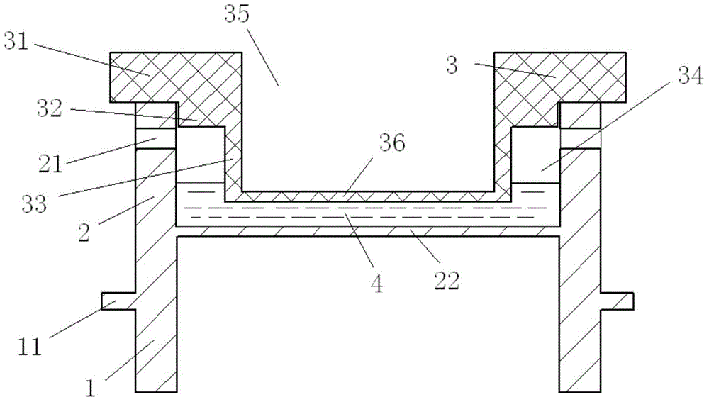
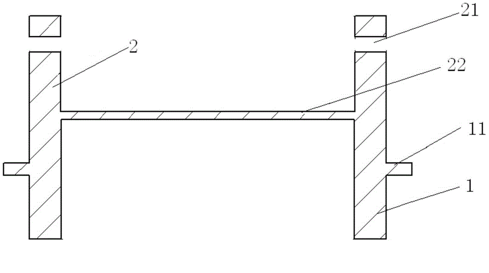
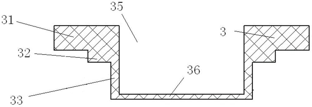

Image

  • Laser flash method-based thermal diffusion coefficient test device and method
  • Laser flash method-based thermal diffusion coefficient test device and method
  • Laser flash method-based thermal diffusion coefficient test device and method

Examples


example 1

[0032] Example 1: KNO 3 Measurement of thermal diffusivity

[0033] Pure take 2~3g pure (purity is 99.9%) KNO 3 Molten salt powder is pressed into flakes and placed in a sample dish, and repeatedly melted and cooled for 3 times under the condition of less than 100Pa to ensure KNO 3 After there are no visible bubbles in the molten salt, the molten salt sample and the sample dish are transferred to the LFA1000 laser thermal conductivity meter, and the test is carried out under the protective atmosphere of He gas. Three tests were carried out at 350°C, 400°C, and 450°C respectively. The test results are as follows: Figure 4 shown, from Figure 4 KNO can be seen in 3 The thermal diffusivity increases with increasing temperature, and the relative standard deviation of three tests is less than 4%. Pure KNO tested by Ohta and other scholars 3 The value of thermal diffusivity of molten salt is 1.4×10 -3 cm 2 / s~1.6×10 -3 cm 2 Within the / range, it is consistent with the re...

example 2

[0034] Example 2: Li 2 CO 3 -Na 2 CO 3 -K 2 CO 3 Measurement of thermal diffusivity of eutectic salt

[0035] Will Li 2 CO 3 -Na 2 CO 3 -K 2 CO 3 The pure (99.9% purity) molten salt powder was dried at 300°C for 24 hours at high temperature. After removing the water, the three pure molten salts were fully mixed according to the ratio of 32.12:33.36:34.52wt.%. Under an inert atmosphere, Cool at 450°C for 48 hours to prepare Li 2 CO 3 -K 2 CO 3 -Na 2 CO 3 (abbreviated as (Li, Na, K) 2 CO 3 ) eutectic molten salt. Take 2~3g (Li, Na, K) 2 CO 3 The molten salt is mechanically ground into powder under the condition of isolating water and oxygen, and under the condition of isolating water and oxygen, the (Li, Na, K) 2 CO 3 The powder is compressed into a thin disc with a thickness of 1.5-3 mm and a diameter of 23 mm, placed in a sample dish and covered with a lid. will be filled with (Li,Na,K) 2 CO 3 The sample dish of molten salt is transferred to the furna...

example 3

[0036] Example 3: Measurement of thermal diffusivity of LiF-KF-NaF eutectic salt

[0037] Pure (99.9% pure) LiF, KF, and NaF powders were fully mixed and melted according to the eutectic molten salt composition, kept at 50°C above the eutectic temperature for 8 hours, cooled, and the molten salt was taken out. After chemical composition analysis, LiF, The ratios of KF and NaF are 11.5mol%, 46mol%, and 42.5mol%, indicating that the prepared molten salt is a eutectic molten salt (marked as FLiNaK). Prepare 2-3g of bulk FLiNaK molten salt into powder under the condition of isolating water and oxygen, and press it into thin slices, place it in a sample dish, and repeat heating, melting and cooling in a heating furnace with a vacuum degree lower than 100Pa for 3~ Take it out after 10 times, and observe that there are no visible bubbles in the FLiNaK molten salt, and it is in complete contact with the upper and lower surfaces of the sample dish. Put the prepared sample in the sampl...


PUM

PropertyMeasurementUnit
thicknessaaaaaaaaaa
thicknessaaaaaaaaaa
diameteraaaaaaaaaa

Abstract

The invention provides a laser flash-based thermal diffusion coefficient test device and method. The laser flash-based thermal diffusion coefficient test device comprises a laser conductometer, a base which is fixed on the laser conductometer, a sample vessel which is arranged at the top of the base and a cover covering the sample vessel, wherein a cut-through degassing hole is formed in the side wall of the sample vessel; the cover consists a first section, a second section and a third section, the diameters of which are gradually decreased; the bottom surface of the first section leans against the top surface of the sample vessel; an overflow space is formed between the outer surface of the third section and the inner surface of the sample vessel; the overflow space is communicated with the external environment through the degassing hole. According to the laser flash-based thermal diffusion coefficient test device, the overflow space formed between the outer surface of the third section and the inner surface of the sample vessel leaves a warming inflation space for samples, so that the samples are prevented from overflowing out of the sample vessel to influence the test result. In the test process, the gas in the samples is discharged from the overflow space to the external environment through the degassing hole, so that isotropic and uniform samples can be prepared.

Description

technical field [0001] The present invention relates to the test of thermal diffusivity, more specifically to a thermal diffusivity test device and method based on laser flash method. Background technique [0002] Thermal diffusivity is the ratio of the thermal conductivity of a substance to its specific heat capacity and density, which characterizes the ability of heat transfer in an object and is an important physical parameter of unsteady heat conduction. Specific heat capacity and density are the properties of the substance itself, and the test method is very mature. Therefore, as long as the thermal diffusivity of the substance is tested, the thermal conductivity can be determined. Thermal diffusivity / thermal conductivity is of great significance in chemical engineering, engineering thermophysics, mechanical engineering, cryogenic engineering, metrology, materials science and other disciplines. Studying the thermal diffusivity / thermal conductivity of fluids is not only...

Claims


Application Information

Patent Timeline
Patent Type & Authority Applications(China)
IPC IPC(8): G01N25/20
Inventor 安学会程进辉张鹏唐忠锋左勇谢雷东
Owner SHANGHAI INST OF APPLIED PHYSICS - CHINESE ACAD OF SCI
Learn More