Wet etching method and device for solar cells

A technology of solar cells and wet etching, which is applied in the field of solar cells, can solve the problems of increasing the production cost and high processing cost of solar cells, and achieve better cleaning effect, reduce water volume, and reduce emissions

Inactive Publication Date: 2015-03-11
TAINERGY TECH KUNSHAN
View PDF5 Cites 11 Cited by
  • Summary
  • Abstract
  • Description
  • Claims
  • Application Information

AI Technical Summary

Problems solved by technology

[0005] In view of the above-mentioned shortcomings of the prior art, the object of the present invention is to provide a wet etching method and device for solar cell sheets, which is used to solve the problem of a large amount of solar cell sheet wet etching method and device in the prior art producing Nitrogen wastewater makes the treatment cost relatively high and raises the production cost of solar cells

Method used


Image

  • Wet etching method and device for solar cells
  • Wet etching method and device for solar cells

Examples


Embodiment 1

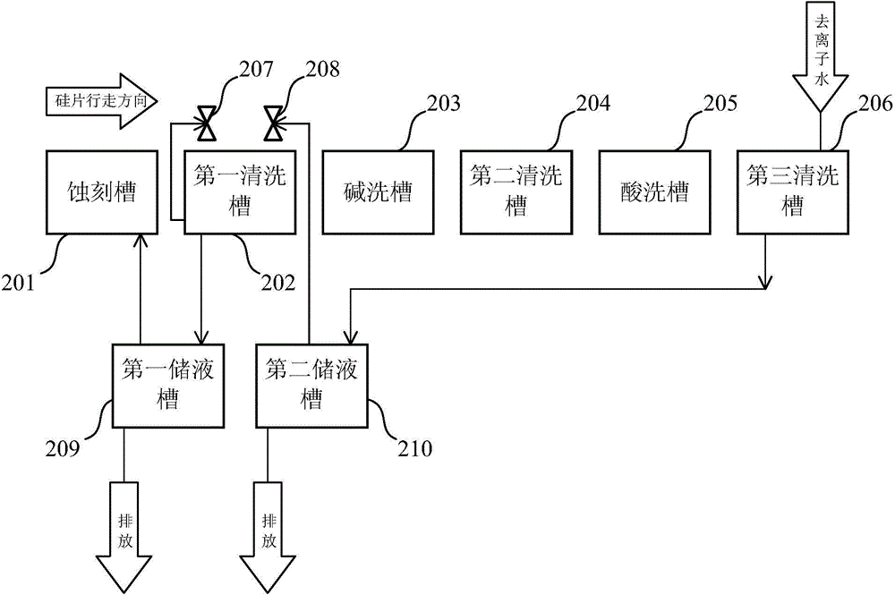
[0042] The invention provides a wet etching device for solar cells, please refer to figure 2 , is shown as a structural schematic diagram of the device, including an etching tank 201, a first cleaning tank 202, an alkali cleaning tank 203, a second cleaning tank 204, an acid cleaning tank 205 and a third cleaning tank 206 placed in sequence; A first water jet 207 and a second water jet 208 are respectively installed at the entrance and exit of the tank 202; wherein:

[0043] The wet etching device further includes a first liquid storage tank 209 and a second liquid storage tank 210 .

[0044]Specifically, the second liquid storage tank 210 is respectively connected to the third cleaning tank 206 and the second water knife 208 through connecting pipes, and when the liquid in the third cleaning tank 206 reaches a preset water level, Drain excess liquid to the second liquid storage tank 210, and the second liquid storage tank 210 supplies liquid to the second water knife 208; ...

Embodiment 2

[0054] The present invention also provides a kind of wet etching method of solar battery sheet, comprises the following steps:

[0055] Firstly, a solar battery is provided. In this embodiment, the solar battery is taken as an example of a silicon wafer.

[0056] Then, the solar cells are sequentially passed through the etching tank 201, the first cleaning tank 202, the alkali cleaning tank 203, the second cleaning tank 204, the pickling tank 205 and the third cleaning tank 206 through the conveying device;

[0057] in:

[0058] The entrance and exit of the first cleaning tank 202 are respectively equipped with a first water knife 207 and a second water knife 208; when the solar cells reach the first cleaning tank 202, the first water knife and the second water jet spray-clean the front and back of the solar cell sheet respectively;

[0059] The third cleaning tank 206 is connected to the second liquid storage tank 210 through a connecting pipeline, and the deionized water i...


PUM


Abstract

The invention provides a wet etching method and device for solar cells. The wet etching device comprises an etching tank, a first washing tank, an alkaline washing tank, a second washing tank, a pickling tank and a third washing tank. An inlet and an outlet of the first washing tank are provided with a first water jet cutter and a second water jet cutter respectively. The wet etching device further comprises a first liquid storage tank and a second liquid storage tank which are connected with the third washing tank and the second water jet cutter through connecting pipelines, respectively.as liquid in the third washing tank reaches a preset water level, redundant liquid is discharged into the second liquid storage tank which supplies the liquid for the second water jet cutter. The first liquid storage tank is connected with the first washing tank and the etching tank respectively through the connecting pipelines. The first washing tank supplies the liquid for the first water jet cutter. As the liquid in the first washing tank reaches the preset water level, the redundant liquid is discharged into the first liquid storage tank used for supplying water and distributing liquid for the etching tank. By the use of the wet etching method and device, nitrogenous waste water discharge is reduced, and production cost is lowered.

Description

technical field [0001] The invention belongs to the field of solar cells, and relates to a wet etching method and device for solar cells. Background technique [0002] A common crystalline silicon solar cell is composed of a back electrode, a P-type layer composed of semiconductor materials, an N-type layer, a P-N junction, an anti-reflection film, and a front gate electrode. When sunlight hits the surface of the solar cell, the anti-reflection film and textured structure can effectively reduce the light reflection loss on the surface of the cell. After the semiconductor structure in a solar cell absorbs solar energy. The electrons and holes are excited to generate pairs of electrons and holes. The electrons and holes are separated by the self-built electric field of the P-N junction inside the semiconductor. The electrons flow into the N region and the holes flow into the P region to form a photo-generated electric field. When connected with an external circuit, there is ...

Claims


Application Information

Patent Timeline
Patent Type & Authority Applications(China)
IPC IPC(8): H01L21/67H01L31/18B08B3/02
CPCH01L21/67075H01L31/18Y02P70/50
Inventor 童锐张小刚柯希满杨大谊
Owner TAINERGY TECH KUNSHAN
Why Eureka
Try Eureka