Laser spot trajectory extracting and displaying device and method

A trajectory extraction and laser spot technology, which is applied in the direction of closed-circuit television systems, etc., to achieve the effect of convenient use, improving the efficiency of debugging and factory work acceptance

Inactive Publication Date: 2015-03-11
HUBEI ENG UNIV
View PDF2 Cites 7 Cited by
  • Summary
  • Abstract
  • Description
  • Claims
  • Application Information

AI Technical Summary

Problems solved by technology

However, there is currently no product on the market that can collect and display the laser spot movement trajectory in real time for the acceptance of laser processing equipment or performance equipment

Method used


Image

  • Laser spot trajectory extracting and displaying device and method
  • Laser spot trajectory extracting and displaying device and method
  • Laser spot trajectory extracting and displaying device and method

Examples


Embodiment Construction

[0021] In order to make the technical means, creative features, goals and effects achieved by the present invention easy to understand, the present invention will be further elaborated below in conjunction with illustrations and specific embodiments.

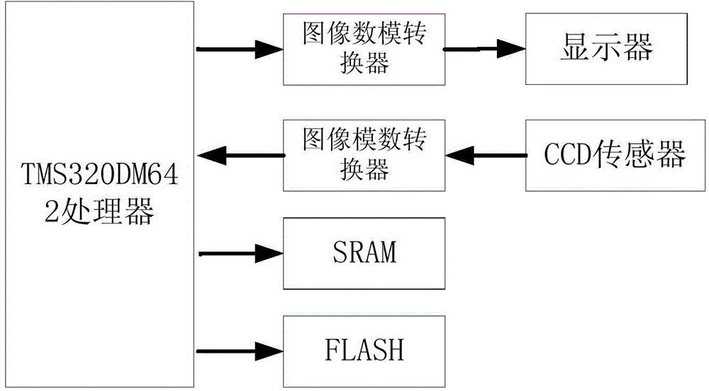
[0022] Such as figure 1 As shown, the laser spot trajectory extraction and display device based on TMS320DM642 includes a processor, image analog-to-digital converter (ADC), image digital-to-analog converter (DAC), display, CCD sensor, externally expanded SRAM and FLASH.

[0023] The processor adopts TMS320DM642 image processor, which is mainly responsible for the realization of the spot trajectory extraction algorithm and the real-time display of the trajectory.

[0024] The image analog-to-digital converter (ADC) uses a video decoder SAA7115 chip, which is used to convert the analog signal output by the CCD sensor into a digital signal in BT.656 format.

[0025] Image digital-to-analog converter (DAC) adopts video encoding ch...


PUM


Abstract

The invention discloses a laser spot trajectory extracting and displaying device and method, wherein the device includes an image processor, an ADC image analog-digital converter, a DAC image analog-digital converter, a display, a CCD sensor, a storage module; an analog signal output from the CCD sensor is converted into a digital signal by the ADC image analog-digital converter, and the signal is transmitted to an image processor for image processing. The processed image is converted into a PAL or NTSC standard analog television signal by the DAC image analog-digital converter, and then output by the display. The storage module is connected to the image processor for increasing storage space of the image processor. The invention has an advantage of being convenient in use. The device and method can collect and display quickly the trajectory of the laser spot, and thus further determines whether the laser scan trajectory of a device complies with a predetermined trajectory. The invention may improve greatly laser processing and debugging of a laser performance equipment and the factory acceptance efficiency.

Description

technical field [0001] The invention relates to the field of optoelectronics, in particular to the extraction and display of laser spot tracks. Background technique [0002] With the development of laser technology, the application of laser scanning technology in the field of manufacturing marks the birth of a new interdisciplinary and cross-industry science. As the main application of laser scanning technology, galvanometer laser scanning is widely used in laser marking, medical diagnosis, laser demonstration, laser processing and other fields due to its high precision and high speed. [0003] During the production and debugging of laser processing equipment or laser performance equipment or factory acceptance, it is necessary to record the trajectory of the laser spot that the laser hits on the workbench or wall in real time to judge whether the laser scanning trajectory of the equipment conforms to the predetermined trajectory. Observation in the background is of great s...

Claims


Application Information

Patent Timeline
Patent Type & Authority Applications(China)
IPC IPC(8): H04N7/18
Inventor 肖永军丁幺明李纪平熊曾刚易青松黄永林马洪华
Owner HUBEI ENG UNIV
Why Eureka
Try Eureka