
A method of obtaining DC pulse high voltage applied to grid-controlled x-ray tube

A pulsed high-voltage, applied technology, applied in the field of X-ray imaging, can solve the problems of soft rays harming the human body and the charge at the load end can not disappear instantly, and achieve the effect of reducing product cost and reducing damage

Active Publication Date: 2017-02-15
BEIJING AILI TECH
View PDF8 Cites 0 Cited by
  • Summary
  • Abstract
  • Description
  • Claims
  • Application Information

AI Technical Summary

Problems solved by technology

[0007] The technical problem to be solved by the present invention is to provide a method for obtaining a DC pulse high voltage applied to a grid-controlled X-ray tube, which overcomes the problem in the prior art that the capacitor at the load terminal accumulates a large amount of charge when the pulse high voltage stops. Defects that disappear instantly and produce a large number of soft rays that cause harm to the human body

Method used


Image

  • A method of obtaining DC pulse high voltage applied to grid-controlled x-ray tube
  • A method of obtaining DC pulse high voltage applied to grid-controlled x-ray tube
  • A method of obtaining DC pulse high voltage applied to grid-controlled x-ray tube

Examples


Embodiment 1

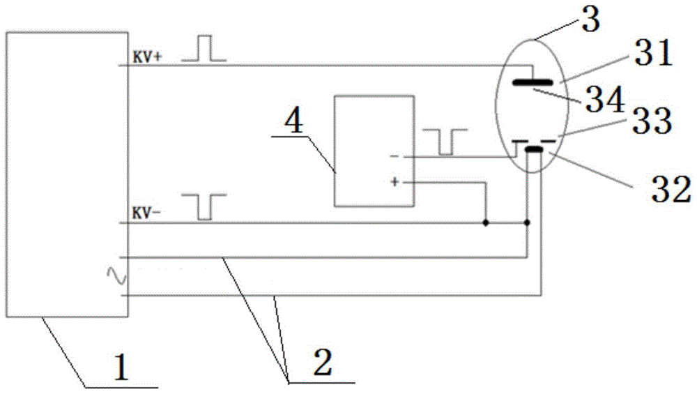
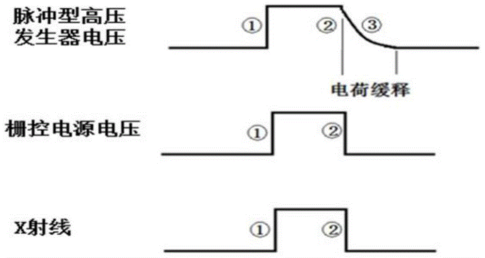
[0041] Such as figure 1 and image 3 As shown, a method for obtaining a DC pulsed high voltage applied to a grid-controlled X-ray tube in the present invention includes the following steps: starting the pulsed high-voltage generator, the grid-controlled power supply outputs a negative high voltage to the grid, and the rotating anode of the tube starts to accelerate Rotate, wait for the rotating anode to accelerate to the specified speed, the negative voltage of the grid control power supply is canceled, and at the same time (or delayed) the pulse high voltage generator starts the high voltage, at this time the high voltage directly reaches the cathode filament of the bulb and the anode target disk, because the grid is in conduction In the state, the electrons generated by the cathode filament quickly pass through the grid and bombard the anode target disk, generating X-rays at the focal point. When the set high-voltage time arrives, the pulse high-voltage generator stops out...

Embodiment 2

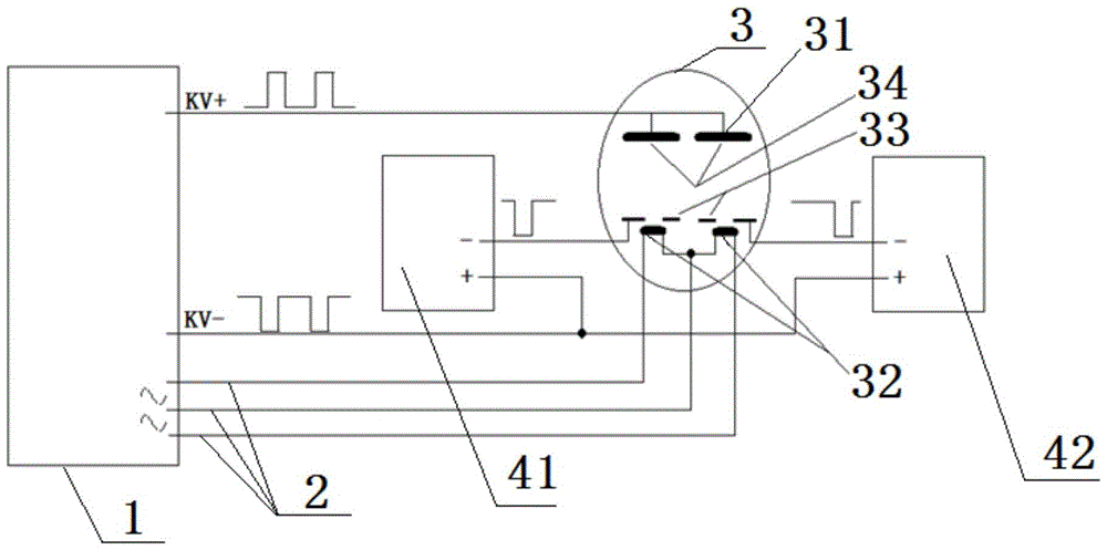
[0045] Such as figure 2 and Figure 4 As shown, a schematic diagram of the structure of the focal point in the tube used in the method for obtaining the DC pulse high voltage applied to the grid-controlled X-ray tube of the present invention, that is, to generate a focus requires a group of grid-controlled power supply, cathode filament and anode target Disk, and between the cathode filament and the anode target disk, there is a set of grids connected to the negative pole of the grid control power supply, and the two sets are arranged in parallel; for example Figure 5 The structure schematic diagram of two sets of grid control power supplies, one cathode filament and two anode target discs is required to generate two focal points as shown, that is, the cathode filament is located in the middle, and the anode target discs are on both sides, and the cathode filament and the anode target disc are set There is a gate connected to the negative pole of the gated power supply. Th...


PUM


Abstract

The invention relates to a method for obtaining a direct-current pulse high voltage applied to a grid-control X-ray bulb tube. The method comprises the following steps that: starting a pulse high-voltage generator, a grid-control power supply outputs a negative high voltage to a grid electrode, a rotating anode of a bulb tube starts to rotate faster, and the negative voltage of the grid-control power supply is eliminated when the rotating anode is accelerated to a regulated rotating speed; meanwhile or after a pulse type high-voltage generator starts a high voltage, the high voltage reaches a cathode filament and an anode target plate of the bulb tube directly, and because the grid voltage becomes zero in a conduction state, the electron generated by the cathode filament passes through the grid and bombards the anode target plate, and an X ray is generated at a focus; when time reaches the set high-voltage one, the pulse type high-voltage generator stops to output the high voltage and the grid-control power supply outputs a negative voltage loaded to the grid electrode, so that the electron beam is cut off immediately. During the process, no harmful soft ray is generated and thus injuries on the human bodies can be reduced, so that an active effect for patients is realized.

Description

technical field [0001] The invention specifically relates to a method for obtaining a DC pulse high voltage applied to a grid-controlled X-ray tube, and belongs to the field of X-ray imaging methods. Background technique [0002] X-ray products are widely used in the market, and the products used in medical treatment include digital radiography machines, gastrointestinal machines, angiography machines, CT, etc. The ability to generate diagnostic X-rays is a common feature of these products. [0003] Obtaining X-rays requires a high-voltage generator and a tube. The high-voltage generator can generate more than ten thousand volts of DC high voltage, which is loaded between the cathode and anode of the X-ray tube. At this time, a large number of electrons generated by the heated filament at the cathode end of the tube are under the action of the electric field. The anode target surface is bombarded at high speed, and the anode target surface will generate X-rays. In practic...

Claims


Application Information

Patent Timeline
Patent Type & Authority Patents(China)
IPC IPC(8): H05G1/12H05G1/22
Inventor 李跃
Owner BEIJING AILI TECH
Learn More