Heat pump units, air conditioners and refrigerators

A technology of heat pump device and refrigerant, which is applied in refrigerators, heat pumps, refrigeration components, etc. It can solve the problems of maintaining stability, high frequency and low voltage without detailed records, and unable to solve the heating capacity of compressors, so as to prevent insufficient heating and suppress noise effect

Active Publication Date: 2017-05-24
MITSUBISHI ELECTRIC CORP
View PDF12 Cites 0 Cited by
  • Summary
  • Abstract
  • Description
  • Claims
  • Application Information

AI Technical Summary

Problems solved by technology

[0010] However, the technology shown in Patent Document 1 does not describe in detail the high frequency and low voltage, and cannot solve the problem of keeping the heating amount of the compressor stable without being affected by manufacturing differences and environmental differences. question

Method used


Image

  • Heat pump units, air conditioners and refrigerators
  • Heat pump units, air conditioners and refrigerators
  • Heat pump units, air conditioners and refrigerators

Examples


Embodiment approach 1

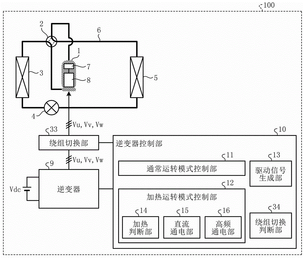
[0094] figure 1 It is a figure which shows the structural example of Embodiment 1 of the heat pump apparatus concerning this invention. Such as figure 1 As shown, the heat pump device 100 of this embodiment includes a refrigeration cycle system in which a compressor 1 , a four-way valve 2 , a heat exchanger 3 , an expansion mechanism 4 , and a heat exchanger 5 are sequentially connected through a refrigerant pipe 6 . Inside the compressor 1 are provided a compression mechanism 7 for compressing refrigerant and a motor 8 for operating the compression mechanism 7 . The motor 8 is a three-phase motor having three-phase windings of U-phase, V-phase, and W-phase.

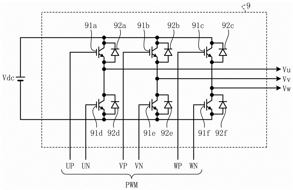
[0095] An inverter 9 that supplies a voltage to drive the motor 8 is electrically connected to the motor 8 via a winding switching unit 33 . The inverter 9 applies voltages Vu, Vv, and Vw to the windings of the U-phase, V-phase, and W-phase of the motor 8 using a DC voltage (bus voltage) Vdc as a power source.

[0...

Embodiment approach 2

[0171] Figure 20 It is a figure which shows the structural example of the winding switching part 33a of Embodiment 2 of the heat pump apparatus concerning this invention. The heat pump device of this embodiment is the same as the heat pump device of Embodiment 1 except that the winding switching unit 33 is replaced with the winding switching unit 33a. Components having the same functions as in Embodiment 1 are given the same symbols as in Embodiment 1, and redundant descriptions are omitted.

[0172] Figure 21 It is a graph showing an example of the relationship between the inductance L and the maximum power Pmax, which is a main factor of impedance in the heating operation mode by high-frequency energization. exist Figure 21 , it is assumed that the bus voltage Vdc is constant. Figure 22 It is a graph showing an example of the voltage command Vk (modulation degree) with respect to the inductance L. exist Figure 22 , it is assumed that the electric power P is consta...

Embodiment approach 3

[0183] Figure 25 It is a figure which shows the structural example of Embodiment 3 of the heat pump apparatus concerning this invention. In this embodiment, an example of a specific configuration and operation when the heat pump device described in Embodiments 1 and 2 are installed in an air conditioner, heat pump water heater, refrigerator, refrigerator, etc. will be described.

[0184] Figure 26 its about Figure 25 A Mollier diagram of the states of the refrigerant in the heat pump device 100 is shown. exist Figure 26 In , the horizontal axis represents the specific enthalpy, and the vertical axis represents the refrigerant pressure.

[0185] The heat pump device 100 of this embodiment includes a compressor 51 , a heat exchanger 52 , an expansion mechanism 53 , a receiver 54 , an internal heat exchanger 55 , an expansion mechanism 56 , and a heat exchanger 57 that are sequentially connected through piping. The main refrigerant circuit 58 of the refrigerant cycle. I...


PUM


Abstract

The present invention provides a heat pump device, which includes: a compressor (1), which compresses refrigerant; a motor (8), which drives the compressor; a winding switching part (33), which switches the winding structure of the motor (8) ; an inverter (9) that applies a desired voltage to the motor (8); and an inverter control unit (10) that generates a PWM signal for driving the inverter (9) as an operation mode that has A heating operation mode in which the compressor (1) performs heating operation and a normal operation mode in which the compressor (1) is normally operated to compress refrigerant, and the switching operation of the winding switching unit (33) is controlled according to the operation modes.

Description

technical field [0001] The present invention relates to a heat pump device having a compressor, an air conditioner and a refrigerator. Background technique [0002] There is known a device that supplies a high-frequency low voltage to a compressor during an operation stop during heating (for example, refer to Patent Document 1). [0003] In addition, there is a device that supplies a single-phase AC voltage with a frequency higher than that during normal operation to the compressor when it is detected that the ambient temperature of the air conditioner is low (for example, refer to Patent Document 2). [0004] There is also a device for preheating using copper loss of a motor winding by performing limited energization through which a direct current flows (for example, refer to Patent Document 3). [0005] In addition, there is a device capable of heating with constant power and low noise regardless of a supplied voltage value by driving an inverter with a drive signal synch...

Claims


Application Information

Patent Timeline
Patent Type & Authority Patents(China)
IPC IPC(8): F25B1/00H02P27/02
CPCF25B13/00F25B49/025H02P27/02F25B2600/021F25B2400/01F25B1/10F25B2400/051F25B2400/054F25B2400/13F25B2500/31F25B2700/2106F25B2700/21156Y02B30/70F25B41/39F25B30/02
Inventor 山川崇畠山和德神谷庄太松下真也楠部真作牧野勉
Owner MITSUBISHI ELECTRIC CORP
Why Eureka
Try Eureka