Method for increasing magnetic field intensity in magnetic field separation area and magnetic separation equipment

A magnetic separation equipment and magnetic field technology, applied in the method and magnetic separation equipment, to improve the field of magnetic field strength in the magnetic field separation area, can solve the problems of low removal efficiency of magnetic objects, no relative movement, and no display of disadvantages, etc., to reduce non-magnetic Effects of inclusion of magnetic substances, improvement of grinding grade, and reduction of adverse effects

Active Publication Date: 2016-09-21
ZHENGZHOU MINERALS COMPOSITIVE UTILIZATION RES INST CHINESE GEOLOGICAL ACAD
View PDF8 Cites 0 Cited by
  • Summary
  • Abstract
  • Description
  • Claims
  • Application Information

AI Technical Summary

Problems solved by technology

When the minerals are transported to the surface of the magnetic roller by the belt, the weakly magnetic minerals located in the white area cannot be effectively captured by the magnetic field, resulting in low removal efficiency of magnetic substances
[0005] In addition, for the conventional magnetic pulley using the above principle, the magnetic minerals are captured by the magnetic field. During the rotation of the magnetic pulley, there is no relative motion between the mineral and the magnetic system. Since the large ore is not easy to be mixed, when processing large ore, the conventional magnetic pulley Shows no technical drawbacks

Method used


Image

  • Method for increasing magnetic field intensity in magnetic field separation area and magnetic separation equipment
  • Method for increasing magnetic field intensity in magnetic field separation area and magnetic separation equipment
  • Method for increasing magnetic field intensity in magnetic field separation area and magnetic separation equipment

Examples


Embodiment 1

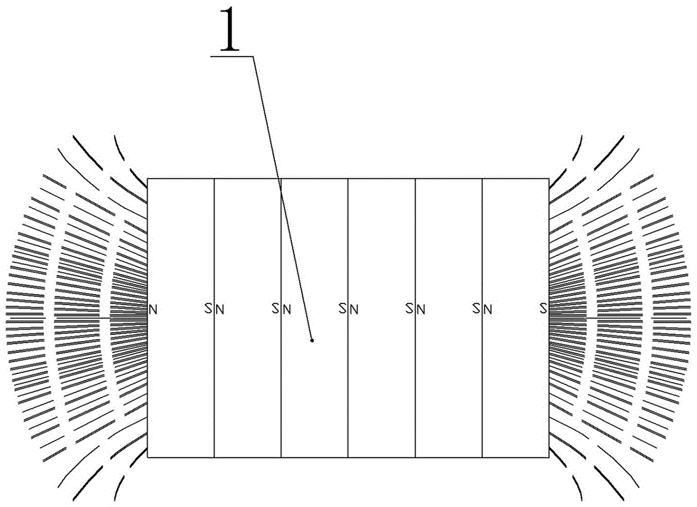
[0040] Embodiment one: see Figure 5-Figure 7 , a method for increasing the magnetic field intensity of the permanent magnet magnetic field sorting area, arrange the N poles and N poles, S poles and S poles of several square permanent magnet blocks 1 with relative gaps one by one, and press them tightly through a fixed frame such as a magnetic system fixing frame The permanent magnetic block group 10 is formed, thereby extruding the original square magnetic block N pole and S pole plane magnetic field into a high-field-strength strip with N poles and S poles alternately arranged along the magnetic block gap of the square magnetic block group magnetic field.

[0041] Several magnetic gathering media are arranged within the effective range of the high field strength strip magnetic field to convert the continuous strip magnetic field into discontinuously distributed magnetic gathering points, thereby further strengthening the field strength of the strip magnetic field.

[0042] ...

Embodiment 2

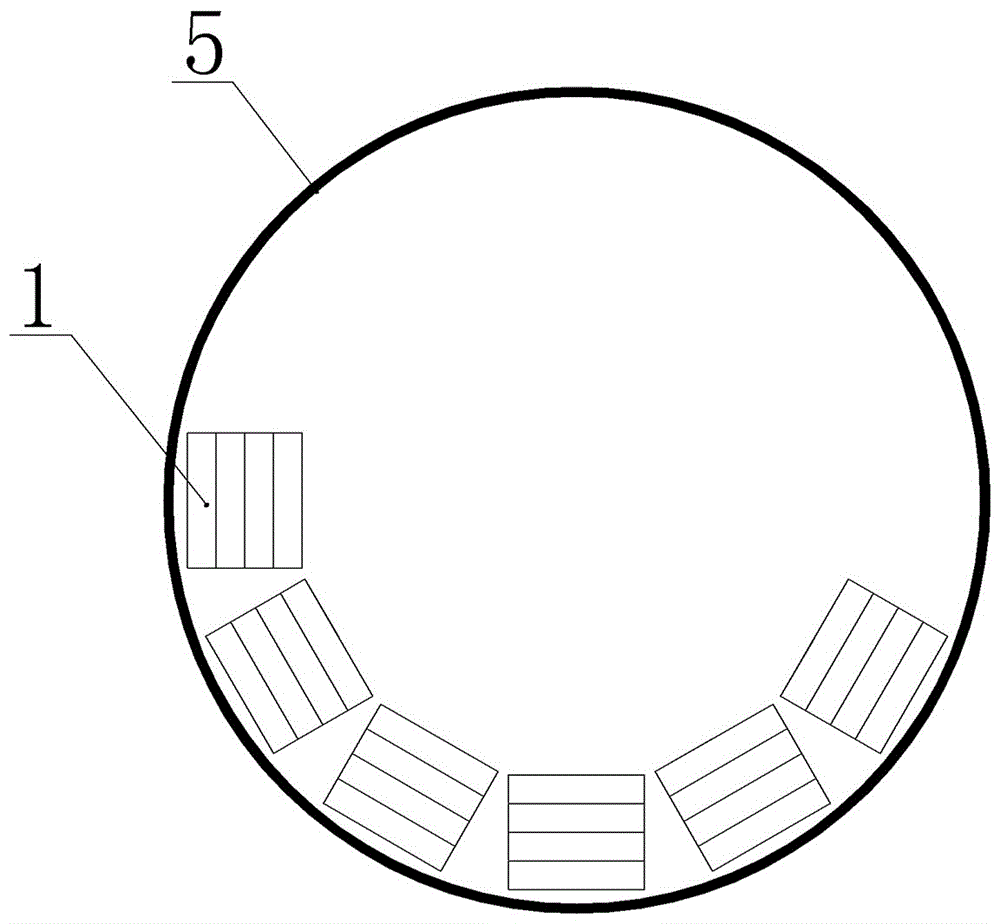
[0043] Embodiment two: see Figure 5-Figure 8 , this embodiment adopts the magnetic system arrangement method described in Embodiment 1 to further complete the magnetic system structure applied to the magnetic separation equipment, which is a strip-shaped strong magnetic field permanent magnetic field that improves the magnetic field intensity of the permanent magnetic field separation area. In the magnetic system, the permanent magnet blocks 10 are continuously arranged in m groups along the sides of a regular polygon with M sides to form N poles and S poles with the center of the regular polygon as the vertex and m×360° / M as the wrap angle The strip-shaped strong magnetic field permanent magnet system arranged densely and alternately, where m≤M, according to different magnetic separation equipment, the wrap angle of the magnetic system is selected according to actual requirements.

Embodiment 3

[0044] Embodiment three: see Figure 5-Figure 9 , a permanent magnetic separation equipment for non-metallic ore iron removal, which is a dry magnetic separation equipment, including a frame 2, a box 4 with a magnetic mineral discharge port 8 at the bottom of the top opening and a box body arranged horizontally 4, the cylindrical barrel 5 in the box body 4 is fixedly provided with a strip-shaped strong magnetic field permanent magnet magnetic system coaxial with the cylindrical barrel 5 by a magnetic system fixing frame 25 on the top of the box body 4, and the strip-shaped strong magnetic field The permanent magnet magnetic system includes m permanent magnet block groups that are continuously distributed along the sides of a regular polygon whose number of sides is M, wherein m


PUM


Abstract

The invention relates to a method and equipment for improving the magnetic field intensity of magnetic selection equipment and provides a method for improving the magnetic field intensity of a magnetic field separation region and magnetic selection equipment. The method and the equipment are based on the following design method: N poles and N poles, and S poles and S poles of a plurality of square permanent magnet blocks are gradually arrayed at intervals and are tightly pressed to form a permanent magnet block group, so that a plane magnetic field of the N poles and the S poles of original square magnet blocks is extruded and converted into a strip-shaped magnetic field in which the magnetic intensity is high, and the N poles and the S poles of the strip-shaped magnetic field are alternatively arrayed along the intervals of the magnet blocks of the square magnet block group. According to the method and the magnetic selection equipment, the magnetic field intensity is multiple times more than that of a conventional magnetic field arraying manner; and a magnetism gathering medium is arranged in an effective range of an extruding magnetic system so that the magnetic field intensity can be further improved, and the application range and the application field can be greatly improved.

Description

technical field [0001] The invention relates to a method and equipment for increasing the magnetic field intensity of magnetic separation equipment, in particular to a method for increasing the magnetic field intensity of a magnetic field separation area and the magnetic separation equipment. Background technique [0002] In the existing field of magnetic mineral magnetic separation technology, since the magnetic field strength of a single magnetic block is often low, the magnetic field generated by the N-pole and S-pole planes on both sides of the magnetic block has a poor ability to capture magnetic minerals. Conventional magnetic separation technology often uses Multiple magnetic blocks are alternately stacked according to N poles and S poles to enhance the magnetic field strength, as shown in the attached figure 1 shown. The magnetic field strength of the magnetic field generated by the N pole and S pole planes on both sides of the magnetic block group is effectively in...

Claims


Application Information

Patent Timeline
Patent Type & Authority Patents(China)
IPC IPC(8): B03C1/02
Inventor 于岸洲
Owner ZHENGZHOU MINERALS COMPOSITIVE UTILIZATION RES INST CHINESE GEOLOGICAL ACAD
Why Eureka
Try Eureka