A steel bridge deck pavement structure and pavement method

A bridge deck pavement and steel bridge deck technology, which is applied to bridges, bridge parts, bridge construction, etc., can solve the problems that ordinary reinforced concrete cannot meet the requirements, the surface tensile strain of the bridge deck pavement is too large, and the bridge deck pavement Insufficient durability and other problems, achieve the effect of improving local cracking, facilitating mechanized construction, and maintaining the same pull-out resistance and shear strength

Active Publication Date: 2016-07-06
NORTH CHINA UNIV OF WATER RESOURCES & ELECTRIC POWER
View PDF6 Cites 0 Cited by
  • Summary
  • Abstract
  • Description
  • Claims
  • Application Information

AI Technical Summary

Problems solved by technology

In the entire orthotropic steel deck structure, the orthotropic structural slab is equivalent to a flexible support. Under the action of the vehicle load, the tensile stress at the local position of the bridge deck pavement reaches 3MPa-7MPa, which is difficult for ordinary reinforced concrete to meet the requirements.
[0004] Because the above-mentioned orthotropic steel bridge deck needs to be arranged with ordinary steel mesh, the manufacturing process is relatively complicated, and there is local stress concentration. Correspondingly, the tensile strain on the surface of the bridge deck pavement is too large, which easily leads to longitudinal and transverse cracking of the bridge deck pavement; 2. The durability of the bridge deck pavement is insufficient. The mixture is easy to creep, thus forming permanent deformation, which will develop into ruts after long-term accumulation; 3. The connection between the bridge deck pavement and the roof is relatively rigid, which may easily cause the concrete near the connection to be crushed and damaged in the early stage of stress ;4. The combination between the bridge deck pavement and the roof is inconsistent with the current usual design assumptions, and the simulation method between the two interfaces is controversial

Method used


Image

  • A steel bridge deck pavement structure and pavement method

Examples


Embodiment Construction

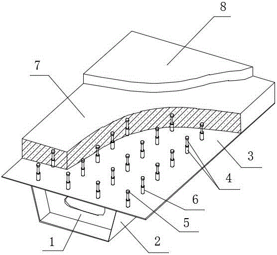
[0021] Such as figure 1 The steel bridge deck pavement structure and pavement method shown include the top plate 3 and the longitudinal web 2 fixedly connected to the bottom surface of the top plate 3 and the transverse diaphragm 1, and the longitudinal web 2 and the transverse diaphragm 1 are connected orthogonally.

[0022] A flexible connector 4 is provided on the top surface of the top plate 3, and the flexible connector 4 is rectangular or quincunx-shaped and uniformly welded on the top plate 3. The flexible connector 4 includes a rigid column 5 and a 1 / 3-3 The flexible cladding body 6 wrapped at the height of / 4, the rigid column 5 and the top plate 3 are vertically welded.

[0023] A bridge deck pavement layer is laid on the top surface of the roof 3, the bridge deck pavement layer includes a steel fiber concrete layer 7 and an asphalt concrete layer 8 laid sequentially from bottom to top, and the top surface of the flexible connector 4 is lower than the bridge deck Th...


PUM


Abstract

The invention discloses a steel bridge deck pavement structure. The steel bridge deck pavement structure is simple and reasonable in structure, a flexible connecting piece is low in shearing rigidity, good in anti-fatigue performance and constant in pull-out capacity and shearing strength, initial shearing rigidity is low, shearing force is kept around one third of the strength with continuous sliding deformation, shearing force value of local fittings can be effectively lowered, stress of bridge deck pavement layer close to rigid pillars is improved, crushing destruction of the bridge deck pavement layer is effectively avoided, the problem about local cracking of the surface of the pavement layer is solved, assumption of common design at present is met, and multiple pavement diseases and problems existing in the steel bridge deck pavement layer at present can be effectively solved. The pavement method is easy and convenient to operate, the pavement layer paved by a steel fiber reinforced concrete layer and an asphalt concrete layer form an integral, tensile capacity is increased, thickness is increased, tensile stress and tensile strain of the surface of the pavement layer can be effectively reduced, and the problem about cracking of the surface of the pavement layer can be effectively solved.

Description

technical field [0001] The invention belongs to the technical field of bridge construction engineering, in particular to a steel bridge deck pavement structure and a pavement method. Background technique [0002] At present, in long-span bridges, orthotropic steel decks are gradually being widely used due to their light component weight, convenient transportation and erection, and short construction period. Most of the existing steel bridge decks use orthotropic steel bridge decks. In other words, longitudinal webs (longitudinal ribs) are welded on the bottom of the top plate of the steel bridge deck, and transverse diaphragms (transverse ribs) orthogonal to it are arranged in the longitudinal webs to form orthotropic structural plates. [0003] The bridge deck pavement is generally composed of a thin layer of reinforced concrete and asphalt concrete laid on the roof, and a steel mesh is laid inside the reinforced concrete. In the entire orthotropic steel deck structure, th...

Claims


Application Information

Patent Timeline
Patent Type & Authority Patents(China)
IPC IPC(8): E01D19/12E01D21/00
CPCE01D19/083E01D19/125E01D21/00
Inventor 刘世明
Owner NORTH CHINA UNIV OF WATER RESOURCES & ELECTRIC POWER
Why Eureka
Try Eureka