Three-phase vortex street current sharing method and device

A vortex street, three-phase technology, applied in chemical instruments and methods, fluid flow, mechanical equipment, etc., can solve the problems of increasing system piezoresistance, increasing system operating costs, etc., to reduce system piezoresistance, reduce resistance, reduce The effect of system resistance

Active Publication Date: 2015-03-25
SHANDONG UNIV
View PDF11 Cites 5 Cited by
  • Summary
  • Abstract
  • Description
  • Claims
  • Application Information

AI Technical Summary

Problems solved by technology

However, all the above technologies have shortcomings. First, the delta wing technology itself utilizes blunt body structures on both the windward and leeward sides. It can be said that the current equalization is achieved on the premise of sacrificing the system resistance, which greatly increases the operating cost of the system
In addition, the delta wing flow equalization in the SCR system mainly focuses on the multiphase mixing of the external fluid and the fluid in the pipeline. However, if the fluid inside the pipeline itself is a multiphase fluid, how to achieve multiphase without the forced mixing of the external fluid? Phase average current is not mentioned

Method used


Image

  • Three-phase vortex street current sharing method and device
  • Three-phase vortex street current sharing method and device
  • Three-phase vortex street current sharing method and device

Examples


Embodiment 1

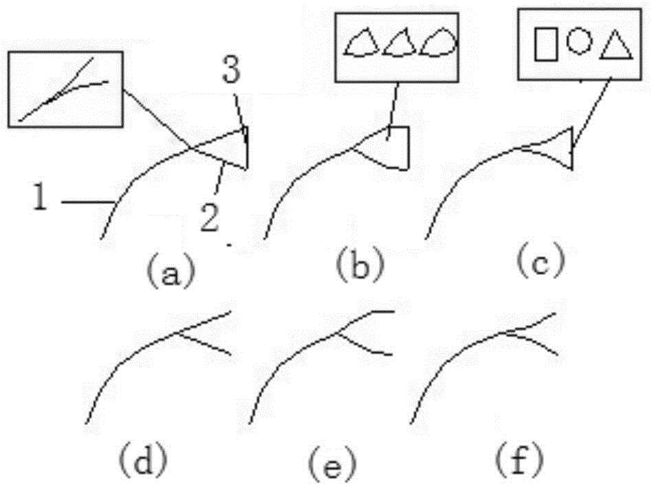
[0032] Such as figure 1 As shown in (a), a three-phase vortex street current sharing device includes a front-end deflector 1 and a three-phase vortex street current sharing baffle, and the windward surface of the three-phase vortex street current sharing baffle is streamlined. Structure 2, the leeward side of the three-phase vortex flow sharing baffle is a bluff body structure 3; the front-end deflector 1 is connected to the streamline structure end of the three-phase vortex flow sharing baffle. It can be directly connected to the conventional baffle or used alone.

[0033] The streamline structure 2 of the three-phase vortex street current sharing baffle is linear (such as figure 1 In (a)), arc (such as figure 1 In (b) shown) or inner hyperbolic (such as figure 1 As shown in middle (c)), the shape of the streamlined body will affect the piezoresistance of the entire system, as well as the form of the rear vortex street.

[0034] The streamline body structure 2 of the three-phase v...

Embodiment 2

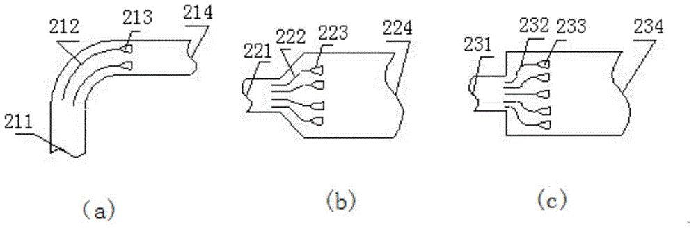
[0039] Example 2: The action process of the three-phase vortex street current equalization device in the turning road, diverging pipeline and sudden expansion pipeline

[0040] by figure 2 As shown, the three-phase vortex street current sharing device is in the turning road ( figure 2 (A)), gradually expanding pipeline ( figure 2 (B)) and sudden expansion pipeline ( figure 2 The arrangement form in (c)); taking the turning pipe as an example, when the airflow enters the turning from the inlet 211, the multiphase flow passes through the front baffle 212 (different forms of baffle are set according to different pipe forms) , To realize the primary gas phase flow equalization, and then, on the basis of the primary gas phase flow equalization, the fluid flows on the windward side streamline body and the leeward side bluff body structure of the three-phase vortex street flow sharing baffle 213 (designed according to the speed difference of each part of the inlet section Three-phase...

Embodiment 3

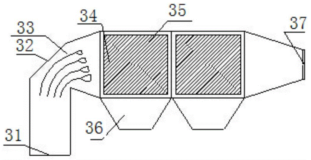
[0042] Example 3: Application of three-phase vortex current sharing device in electrostatic precipitator

[0043] image 3 In order to set up the three-phase vortex flow equalizing plate of the electrostatic precipitator of the present invention, the coal-fired flue gas enters from the inlet 31 and flows through the right-angled bend 32, and the gas-solid two-phase flow is in the three-phase vortex flow equalization device 33. According to the speed difference of each part of the inlet section of the dust collector, a three-phase vortex flow sharing baffle with different sizes and densities is designed to achieve high efficiency three-phase flow sharing. The number of three-phase vortex flow sharing devices 33 and the pipeline The pipe diameter ratio is: 5 / 3600mm, and the separation distance between the three-phase vortex current sharing devices 33 is 300-600mm. Under the action of the three-phase vortex flow equalization device 33, the two phases are uniformly mixed, and the ev...


PUM


Abstract

The invention discloses a three-phase vortex street current sharing device which comprises front-end flow guide boards and three-phase vortex street current sharing baffles. The windward faces of the three-phase vortex street current sharing baffles are each of a streamline body structure. The leeward faces of the three-phase vortex street current sharing baffles are each of a bluff body structure. The front-end flow guide boards are connected with the streamline body structure ends of the three-phase vortex street current sharing baffles which can be used for achieving the increased vortex street current sharing effect in a corner or a gradually-expanding pipeline or a suddenly-expanding pipeline. The windward faces of the three-phase vortex street current sharing device are each of the streamline body structure, resistance in the gas, liquid and solid three-phase movement processes is fully reduced, the pressure drop and the energy consumption of a system are reduced, and operation cost is reduced; the leeward faces are each of the bluff body structure, so that when gas, liquid drops and particles flow through bluff bodies, two-way vortex streets are generated behind the bluff bodies, the flow field turbulence behind the current sharing baffles is improved, and the three phases are more evenly mixed through transverse conveyance of the vortex streets.

Description

Technical field [0001] The invention relates to a three-phase vortex street current equalization method and a device thereof, and belongs to the technical field of fluid flow. Background technique [0002] In the pipeline of industrial equipment, the reverse change of the pipe section and the change of the pipe direction will cause the fluid movement direction to change, which will cause the liquid phase or solid particle phase carried by the fluid to separate, and finally make the fluid flow through sharp bends, divergent pipes or sudden changes. The uneven cross-sectional velocity / concentration distribution after pipe expansion further affects the working efficiency of subsequent equipment such as mixing, transfer, and reaction. If the fluid flows through the entrance elbow section, divergent section or sudden expansion section, the use of a properly designed flow equalizing device can greatly avoid these adverse effects, maintain the air flow pattern, and make the air flow vel...

Claims


Application Information

Patent Timeline
Patent Type & Authority Applications(China)
IPC IPC(8): F16L55/00B03C3/011
CPCB03C3/011F15D1/02F16L55/00
Inventor 马春元潘晓慧崔琳张立强王志强
Owner SHANDONG UNIV
Why Eureka
Try Eureka