Control method of regenerative combustion equipment

A technology of combustion equipment and control method, which is applied to combustion methods, combustion equipment, lighting and heating equipment, etc., can solve the problems of flue gas temperature affecting the safe operation of environmental protection devices, large furnace pressure fluctuations, and long commutation time. There is a large excess of combustion-supporting gas, the furnace pressure is stable, and the effect of avoiding explosion and explosion

Active Publication Date: 2015-03-25
HUNAN BALING FURNACE ENERGY CONSERVATION
View PDF6 Cites 1 Cited by
  • Summary
  • Abstract
  • Description
  • Claims
  • Application Information

AI Technical Summary

Problems solved by technology

In this kind of regenerative combustion system with paired distributed burners, since the pipe space used to provide combustion-supporting gas for combustion is equal to the flue gas pipe space used for smoke exhaust, the combustion-supporting gas and fuel are mixed and burned to produce The volume of flue gas will increase, and the volume of flue gas under standard conditions is at least 1.1-1.3 times the volume of combustion-supporting gas. High voltage, unsafe state
The existing solution is to add an auxiliary flue to the furnace body to allow about 30% of the high-temperature flue gas to be discharged directly, but this will cause the total waste heat recovery rate of the flue gas to be only 50%-60%, and the exhaust gas temperature is too high Will directly affect the safe operation of environmental protection devices
[0004] In addition, when the control method of the traditional regenerative combustion equipment changes direction, not only the furnace pressure fluctuates greatly, but also the phenomenon of detonation and explosion is very easy to occur, and the changeover time is longer, resulting in serious waste of fuel

Method used


Image

  • Control method of regenerative combustion equipment
  • Control method of regenerative combustion equipment
  • Control method of regenerative combustion equipment

Examples


Embodiment Construction

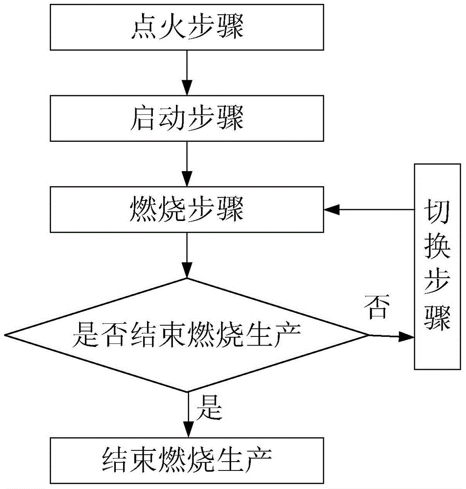
[0064] The control method of the regenerative combustion equipment provided by the present invention includes an ignition step, a start-up step, a combustion step, a switching step and a circulation step, such as image 3 shown. A control method of the regenerative combustion equipment of the present invention and its various steps will be described in detail below.

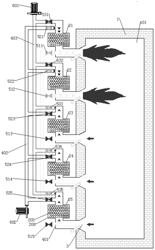
[0065] In one embodiment, the regenerative combustion equipment includes five regenerative burners arranged in sequence, that is, the first regenerative burner 21, the second regenerative burner 22, the third regenerative burner 23. The fourth regenerative burner 24 and the fifth regenerative burner 25, two of which are used for combustion and three for smoke exhaust. Set the working time of each regenerative burner for combustion to 60s, then the switching interval is 60s / 2=30s.

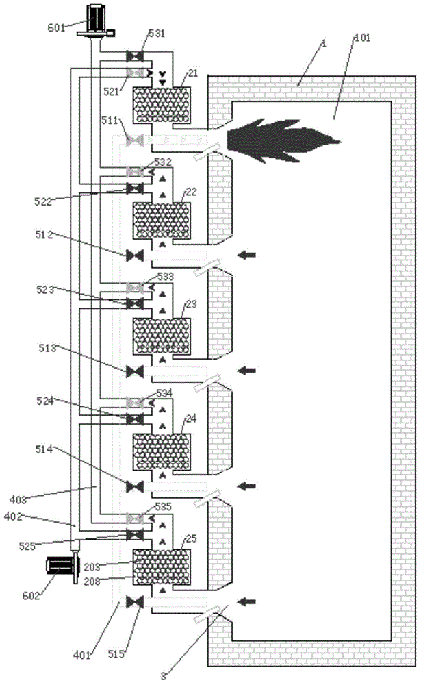
[0066] The ignition step involves first firing a regenerative burner, such as figure 2 shown. In this embodiment, the controller...


PUM


Abstract

The invention provides a control method of regenerative combustion equipment. The method includes an igniting step, a starting step, a combustion step and a switching step. The method overcomes the technical bias that the regenerative combustion equipment is controlled in pairs with a traditional method and achieves an unexpected energy-saving technical effect, and the phenomena that in an existing high-temperature air combustion technology, detonation and furnace explosion happen easily in the reversing process, and fuel waste is serious are effectively avoided.

Description

technical field [0001] The invention relates to a control method of combustion equipment, in particular to a control method of regenerative combustion equipment. Background technique [0002] Industrial furnaces are the main energy-consuming equipment in industrial production, and the energy consumption accounts for 60% of the total industrial energy consumption. Therefore, the research on its energy-saving technology is of great significance. [0003] Existing industrial furnaces generally use regenerative combustion systems to recover and utilize the waste heat of flue gas. However, the regenerative combustion systems currently used at home and abroad are all arranged in pairs, that is, one group of regenerative burners is used for combustion, and the other group of the same number of regenerative burners is used for smoke exhaust, and the timing is reversed. The heat accumulator alternately stores and releases heat. In this kind of regenerative combustion system with pa...

Claims


Application Information

Patent Timeline
Patent Type & Authority Applications(China)
IPC IPC(8): F23N5/00
CPCF23D23/00F23N5/00F23L2900/15022F27D17/004F27D99/0033F23L15/02F23N2237/02Y02E20/34Y02P80/15
Inventor 周绍芳
Owner HUNAN BALING FURNACE ENERGY CONSERVATION
Why Eureka
Try Eureka