
Micromechanical piezoelectric jet gyroscope

An electric jet and micro-mechanical technology, applied in steering induction equipment and other directions, can solve the problems that the volume cannot be too small, which restricts the application and development, and achieves the effect of large driving capacity, simple structure and wide application field.

Inactive Publication Date: 2015-03-25
BEIJING INFORMATION SCI & TECH UNIV
View PDF7 Cites 21 Cited by
  • Summary
  • Abstract
  • Description
  • Claims
  • Application Information

AI Technical Summary

Problems solved by technology

The piezoelectric jet gyroscope in the prior art is generally composed of the housing of the sensitive device, the nozzle body, the sensitive element, the piezoelectric pump, the pump seat, the disc spring, the lock nut and the external circuit system and the mechanical system. The gyroscope is made by traditional mechanical processing technology, and its volume cannot be too small, so it cannot be used in the field of attitude measurement and control of micro-carriers such as helmets and cameras, thus restricting its application and development

Method used


Image

  • Micromechanical piezoelectric jet gyroscope
  • Micromechanical piezoelectric jet gyroscope
  • Micromechanical piezoelectric jet gyroscope

Examples


Embodiment Construction

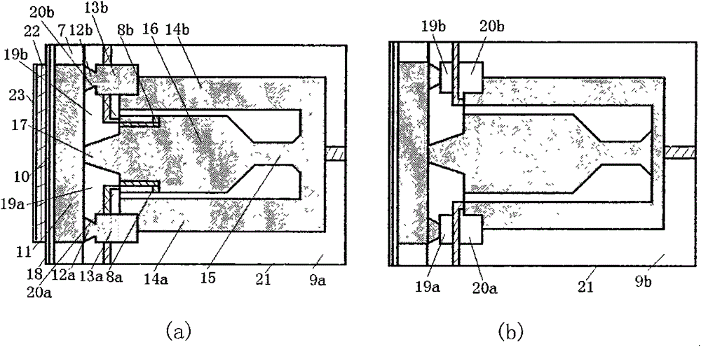
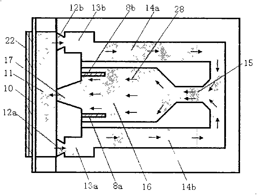
[0026] The premise of the angular velocity sensitivity of the micromechanical piezoelectric jet gyroscope is that the gas circulates in the sensitive element. Whether the gas can circulate mainly depends on the structure and driving capacity of the jet chamber of the piezoelectric pump. The present invention will be further described below in conjunction with the accompanying drawings and specific embodiments.

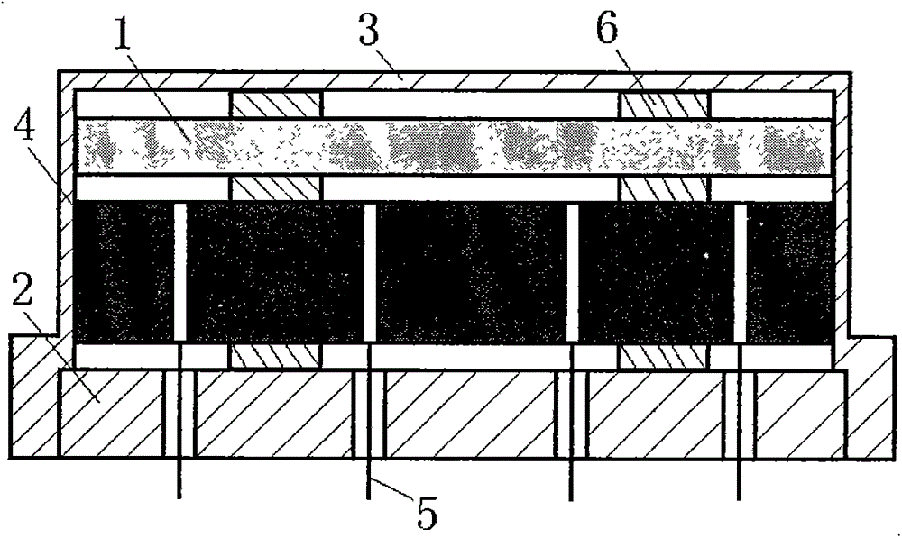
[0027] The micromechanical piezoelectric jet gyroscope of the present invention is made up of sensitive element 1, base 2, shell 3, signal processing circuit 4, insulator 5, spacer 6, and power supply and signal are drawn through the insulator 5 wiring of glass filling on the base 2 (such as figure 1 shown), the sensitive element 1 includes a piezoelectric ceramic micropump 7, a jet gas path and a thin film thermistor 8a, 8b, and is characterized in that:

[0028] The parts of the sensitive element 1 are molded in the silicon plate by micro-mechanical manufacturing pr...


PUM


Abstract

The invention relates to a micromechanical piezoelectric jet gyroscope, which belongs to a micromachining technology manufactured gyroscope generating jet flow by a piezoelectric pump, and is used for the stable system of robots, helmets, cameras and other micro-carriers. The jet gyroscope provided by the invention is composed of a sensitive element, a base, a shell, a signal processing circuit, insulators and gaskets. The power supply and signal are led out through wiring of the glass filled insulators on the base. The sensitive element comprises a piezoelectric ceramic micropump, a jet cavity and Pt film thermistors, and is formed by bonding of an upper silicon plate and a lower silicon plate. The upper silicon plate is provided with a vibrating diaphragm, a pump chamber, the jet cavity and the Pt film thermistors, and the lower silicon plate has a structure symmetric with the upper silicon plate but has no Pt film thermistor. The lower silicon plate is coated with an electrode and is bonded with the upper silicon plate to form the airtight jet cavity. The signal processing circuit consists of a piezoelectric pump drive circuit, a bridge circuit, an amplification circuit, a filter circuit and a compensation circuit.

Description

technical field [0001] The invention belongs to the technical field of angular velocity and attitude measurement of a moving body, in particular to the technical field of micromechanical piezoelectric jet gyroscopes manufactured by micromachining techniques. Stabilization systems for micro-carriers such as robots, helmets, cameras, etc. Background technique [0002] The piezoelectric jet gyro device is a solid-state inertial device that has the function of a gyro without the rotating part of the traditional gyro and without the suspension parts of the piezoelectric gyro. Piezoelectric jet gyro uses gas as the sensitive mass, and its mass is extremely small. It uses Coriolis force to deflect the circulating airflow beam to realize the measurement of angular parameters. It has the advantages of low cost, short response time, strong impact resistance, and long life. The piezoelectric jet gyroscope in the prior art is generally composed of the housing of the sensitive device, t...

Claims


Application Information

Patent Timeline
IPC IPC(8): G01C19/58
CPCG01C19/58
Inventor 朴林华陈敬波
Owner BEIJING INFORMATION SCI & TECH UNIV
Learn More