Intelligent card and mobile terminal battery composite structure
A mobile terminal and composite structure technology, applied in the field of smart cards, can solve the problems affecting the signal data transmission of contactless smart cards, etc., and achieve the effect of improving sensitivity and data reading and writing distance, easy to carry, saving tedious process and high cost
- Summary
- Abstract
- Description
- Claims
- Application Information
AI Technical Summary
Problems solved by technology
Method used
Image
Examples
Embodiment 1
[0040] In the smart card described in the first embodiment, as Figure 5 As shown, the contactless chip 32 is circuit-connected with the induction antenna 31 and packaged together in the card body layer 30 made of insulating material; for example, the induction antenna 31 is arranged around the contactless chip 32 .
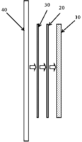
[0041] see figure 1 As shown, taking the case where the sensing area is on the back of the mobile phone as an example, the positional relationship of this part of the mobile phone is the battery 10, the shielding layer 20 of the composite structure, the sensor including the non-contact chip 32 and the sensing antenna 31 from the inside to the outside. Card body layer 30, and mobile phone backplane 40.
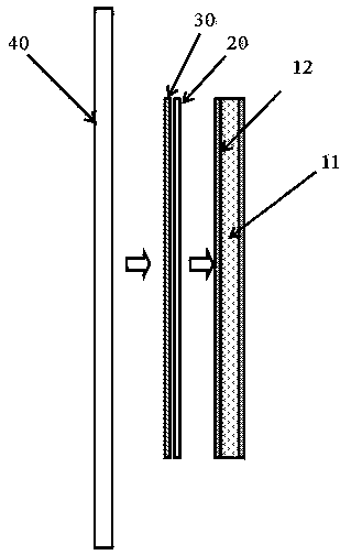
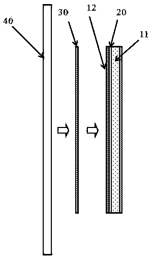
[0042] Such as figure 2As shown, the battery 10 includes a battery body 11 and a packaging layer 12 disposed on the battery body 11 . The outermost part of the battery body 11 is a metal shell; the packaging layer 12 displays text, graphics or a combination th...
Embodiment 2
[0048] The difference in the second embodiment mainly lies in, for example, Image 6 As shown, only the inductive antenna 31 is packaged in the card body layer 30 of the smart card, and the inductive antenna 31 is provided with a contact group 311 drawn out of the card body layer 30, capable of connecting with the card body layer 30 external non-contact chip 32 The electrodes on the antenna are directly or indirectly connected to form a circuit connection between the sensing antenna 31 and the non-contact chip 32 .
[0049] Therefore, in the second embodiment, for the case where the sensing area is on the back of the mobile phone, refer to figure 1 As shown, the mobile phone includes the battery 10 of the composite structure, the shielding layer 20 , the card body layer 30 including the induction antenna 31 , and the back panel 40 of the mobile phone from the inside to the outside. The packaging layer 12 of the battery 10 can be arranged between the battery 10 and the shieldi...
Embodiment 3
[0052] The main difference in the third embodiment is that the battery described is a battery with an NFC structure (hereinafter referred to as an NFC battery). Near-field communication (NFC), also known as short-range wireless communication, is a short-range high-frequency wireless communication technology that allows non-contact point-to-point data transmission between electronic devices; devices with NFC function can be read in active mode. The writing device reads and writes data to other NFC devices or various non-contact chips (not specifically referring to chips in the present invention) based on RFID; while in passive mode, NFC devices are equivalent to ordinary non-contact chips and can be read and written by other NFC devices. read and write device or NFC device to read and write data.
[0053] Such as Figure 7 , Figure 8 The shown NFC battery includes an NFC radio frequency antenna 51 and a shielding layer 20 in addition to the battery body 11 and the packaging ...
PUM
 Abstract
Description
Claims
Application Information
 - R&D
- Intellectual Property
- Life Sciences
- Materials
- Tech Scout
- Unparalleled Data Quality
- Higher Quality Content
- 60% Fewer Hallucinations
Browse by: Latest US Patents, China's latest patents, Technical Efficacy Thesaurus, Application Domain, Technology Topic, Popular Technical Reports.
© 2025 PatSnap. All rights reserved.Legal|Privacy policy|Modern Slavery Act Transparency Statement|Sitemap|About US| Contact US: help@patsnap.com


