Implementation method of laser range-gated imaging high-pulse-width-precision pulse generator

A technology of laser range gating and pulse generator, applied in the direction of electric pulse generator circuit, pulse processing, pulse technology, etc., can solve the problem of bulky and unfavorable range gating imaging control system integration and productization, synchronous control The system is not easy to operate and other problems, to achieve the effect of convenient control and operation, high integration

Active Publication Date: 2015-03-25
INST OF SEMICONDUCTORS - CHINESE ACAD OF SCI
View PDF5 Cites 7 Cited by
  • Summary
  • Abstract
  • Description
  • Claims
  • Application Information

AI Technical Summary

Problems solved by technology

Patent CN102170277A adopts FPGA and delay line to jointly realize the TTL signal with picosecond precision and narrow pulse width to trigger the pulse laser and gate to complete the synchronous control in range gating imaging, because the delay line delay of fixed length is fixed Yes, if you want to realize multiple signals with different pulse widths, you need to use multiple delay lines of different lengths to delay and phase-shift the signals, which means that the synchronous control system is not easy to operate and the volume will be huge, which is not conducive to distance selection. Integration and productization of the control system of communication imaging

Method used


Image

  • Implementation method of laser range-gated imaging high-pulse-width-precision pulse generator
  • Implementation method of laser range-gated imaging high-pulse-width-precision pulse generator
  • Implementation method of laser range-gated imaging high-pulse-width-precision pulse generator

Examples


Embodiment Construction

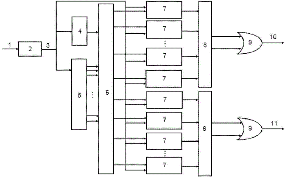
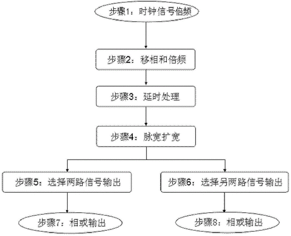
[0035] see figure 1 and figure 2 As shown, the present invention provides a kind of realization method (each method adopts figure 1 Schematic diagram of the structure), including the following steps:

[0036] Step 1: The clock signal 1 is multiplied by the frequency multiplier module 2 to output the multiplied clock signal 3;

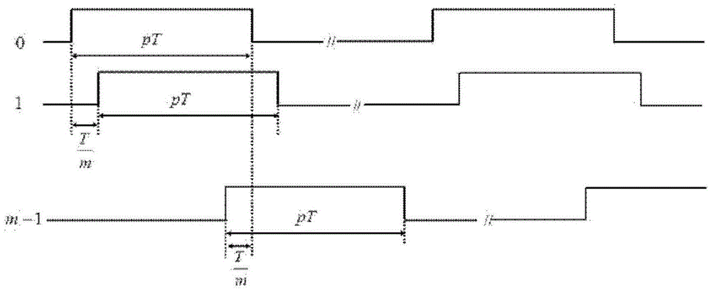
[0037] Step 2: Divide the frequency-multiplied clock signal 3 into two channels, one channel is divided by the frequency divider 4 to obtain a frequency-divided signal, and the other channel is phase-shifted by the phase-shifting module 5 to obtain multiple channels of clock signals with different phases (see image 3 );

[0038] Step 3: Use the multi-channel clock signals with different phases obtained in step 2 as the trigger clock signal to delay the frequency-divided clock signal obtained in step 2 through the delay module 6, and output multiple channels with relative delay The signal; the multiple signals with relative delay are divided into t...


PUM


Abstract

The invention discloses an implementation method of a laser range-gated imaging high-pulse-width-precision pulse generator. The implementation method comprises the steps that frequency doubling is carried out on clock signals, and the clock signals are divided into two paths of signals; with the obtained multiple paths of clock signals with different phases as triggering clock signals, multiple paths of signals with relative time delay are output; the pulse width of the different delayed signals is increased, and signals with the pulse width increased are output; one part of the signals are input into a selector, and two paths of signals are selected to be output; the other part of the signals are input into the selector, and two paths of signals are selected to be output; phase OR is carried out on the two paths of output signals through a logic OR gate, so that high-pulse-width-precision TTL signals are obtained and output; phase OR is carried out on the output signals through the logic OR gate, so that high-pulse-width-precision TTL signals with relative time relay are obtained and output. According to the implementation method, phase OR is carried out on the TTL triggering signals obtained after digital phase-shifting so as to obtain the TTL signals with pulse width precision higher than global clock precision, and therefore high-precision sequence signals can be provided for the laser range-gated imaging field.

Description

technical field [0001] The invention relates to the technical field of laser range gating imaging, in particular to a method for improving pulse width control precision based on digital phase shifting. Background technique [0002] The basis of realizing laser range-gated imaging is to control the pulsed laser and the gate to work synchronously. By controlling the relative delay between the laser pulse and the gating pulse, the gating gate is only opened when the reflected light of the target reaches the gating gate, and the light intensity information containing the target information is recorded, and the gating gate is closed during the light flight time. Record light intensity information. In this way, noises such as scattered light and background light in the light time of flight are avoided from deteriorating the imaging quality, and the detection distance and precision of laser imaging are improved. [0003] The relative delay between the pulsed laser and the gate is...

Claims


Application Information

Patent Timeline
Patent Type & Authority Applications(China)
IPC IPC(8): H03K3/02H03K5/135
CPCG01S7/484
Inventor 卢德贞范松涛王新伟崔伟周燕刘育梁
Owner INST OF SEMICONDUCTORS - CHINESE ACAD OF SCI
Why Eureka
Try Eureka