

Durable solar mirror films
A technology of mirror reflection film and solar energy, which is applied in the direction of solar thermal energy, solar thermal power generation, solar collectors, etc., and can solve the problem that the working temperature is not so high
- Summary
- Abstract
- Description
- Claims
- Application Information
AI Technical Summary
Problems solved by technology
Method used
Image

Examples
example
[0083] testing method :
[0084] Coefficient of hygroscopic expansion (CHE) : Hygroscopic swelling was measured using a Dynamic Mechanical Analyzer (DMA) (Model "Q800" from TA Instruments) in conjunction with a DMA-RH accessory (from TA Instruments). Displacement (in m / m) was measured at a constant temperature of 25°C with varying relative humidity increases of about 20% and about 80%. CHE was calculated using the change in sample size caused by changes in humidity. Results are expressed as parts per million (ppm) / percent relative humidity (RH%).
[0085] Neutral Salt Spray Test (NSS)
[0086] According to ISO 9227:2006, "Corrosion tests in artificial atmospheres--Salt spray tests" (Corrosion tests in artificial atmospheres--Salt spray tests), except that the results are recorded as visual observations after various times The comparative examples and examples were evaluated for corrosion.
example 1
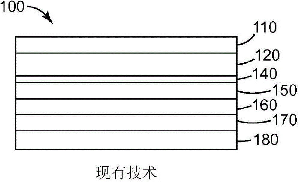
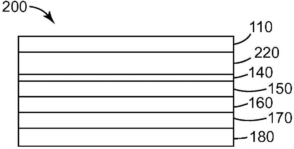
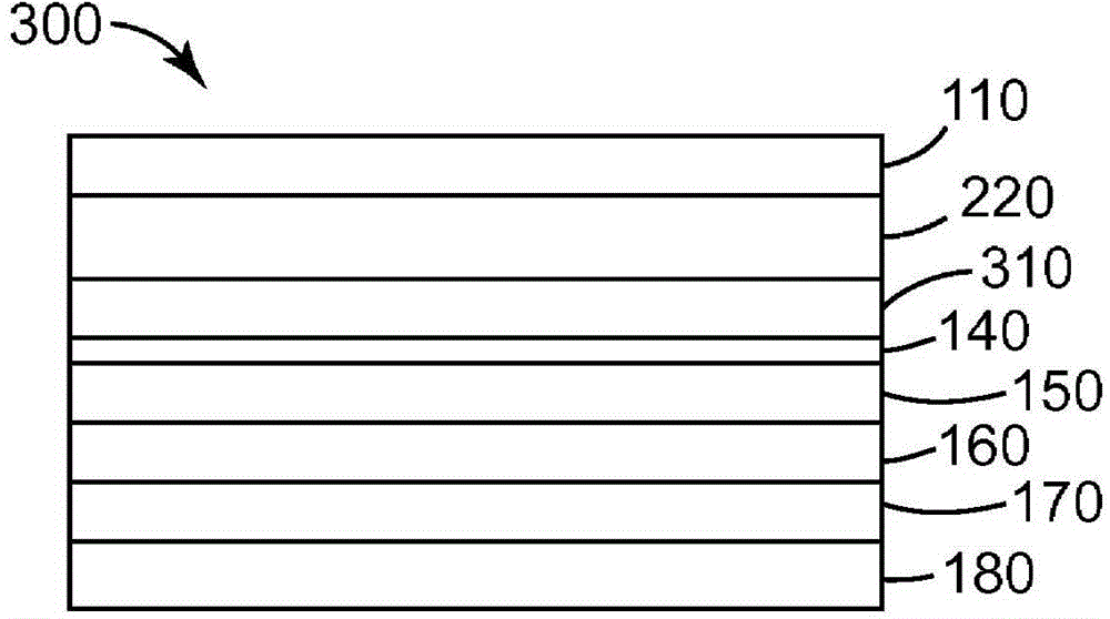
[0090] Multilayer optical films were made as follows: Multilayer optical laminates (described below) were made by coextruding a first polymer layer and a second polymer layer through a multilayer polymer melt manifold to produce Multilayer melt flow of 550 alternating layers. Two skin layers, each having a thickness of approximately 4 microns, were also coextruded as protective layers on each side of the optical layer stack. The multi-layer melt stream is cast onto chilled casting rolls to produce a multi-layer cast web. The multilayer cast web was then heated in a tenter oven to a temperature of about 105°C before biaxially oriented to a draw ratio of 3.8x3.8. A reflective layer of silver approximately 100 nm thick was vapor deposited onto the film substrate. An approximately 80 nm thick layer of copper was coated onto the silver layer. Apply 25 microns of acrylic adhesive to the copper layer. The resulting multilayer optical film was bonded to an epoxy-coated aluminum su...
example 2
[0095] Multilayer optical films were made as follows: Multilayer optical laminates (described below) were made by coextruding a first polymer layer and a second polymer layer through a multilayer polymer melt manifold to produce Multilayer melt flow with 150 alternating layers. Two skin layers, each having a thickness of approximately 4 microns, were also coextruded as protective layers on each side of the optical layer stack. The multi-layer melt stream is cast onto chilled casting rolls to produce a multi-layer cast web. The multilayer cast web was then heated in a tenter oven to a temperature of about 105°C before biaxially oriented to a draw ratio of 3.8x3.8. A reflective layer of silver approximately 100 nm thick may be vapor deposited onto the film substrate. An approximately 80 nm thick layer of copper may be coated onto the silver layer. A 25 micron acrylic adhesive can be applied to the copper layer. The resulting multilayer optical film can be bonded to an epoxy-...
PUM
| Property | Measurement | Unit |
|---|---|---|
| thickness | aaaaa | aaaaa |
| thickness | aaaaa | aaaaa |
| glass transition temperature | aaaaa | aaaaa |
Abstract
Description
Claims
Application Information