Simulating testing device and method for temperature difference-sediment coupling density current of stratified reservoir

A simulation test, density flow technology, applied in the hydraulic model, etc., can solve the problem that there is no feasible method for simultaneous sampling of sediment, the research lag of sediment density flow, and the influence of heating rods on water flow, etc., to achieve excellent followability , Small coefficient of thermal expansion, constant liquid level

Active Publication Date: 2015-04-01
XI'AN UNIVERSITY OF ARCHITECTURE AND TECHNOLOGY
View PDF5 Cites 12 Cited by
  • Summary
  • Abstract
  • Description
  • Claims
  • Application Information

AI Technical Summary

Problems solved by technology

[0004] Sediment is the carrier of many pollutants, dissolved salts, waste heat, etc. The pollutant load carried by the sediment hyperpycnal flow in the rainstorm season generally accounts for more than 70% of the total annual pollutant load of the reservoir. To study how the sediment is transported in the reservoir It plays a very important guiding role in stratified water intake at different elevations in the reservoir, such as municipal water supply and irrigation water, and in maintaining the ecological environment in the reservoir area. However, limited by the development of the physical model of stratified reservoirs and the simultaneous sampling of sediment at different...

Method used


Image

  • Simulating testing device and method for temperature difference-sediment coupling density current of stratified reservoir
  • Simulating testing device and method for temperature difference-sediment coupling density current of stratified reservoir
  • Simulating testing device and method for temperature difference-sediment coupling density current of stratified reservoir

Examples


Embodiment

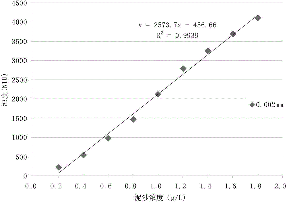
[0051] See image 3 with Figure 4 ,use image 3 The relationship curve shown converts the turbidity of the water sample into sand content, and then uses the sand content data to draw the sediment concentration distribution at different times under different conditions in the model reservoir.

[0052] by Figure 4 It can be seen that when the quartz sand concentration is 5g / L and the inflow velocity is 0.0025m / s, the density flow is an interlaminar flow (between -0.15 and -0.4m), and the position of the interlaminar flow is -0.225m. The thickness of the interlaminar flow is 0.15m, and the position of the interlaminar flow moves down with the passage of time, the thickness increases, and the speed gradually decreases.

[0053] by Figure 5 It can be seen that when the concentration of quartz sand is 2.5g / L and the flow rate is 0.00125m / s, the density flow is surface flow (between 0 and -0.15m).

[0054] by Image 6 It can be seen that when the concentration of quartz sand is 7.5g / L a...


PUM


Abstract

The invention discloses simulating testing device and method for temperature difference-sediment coupling density current of a stratified reservoir. The device comprises a reservoir model, a buffering tank, a muddy water tank, a water draining tank, etc. The method comprises the steps of 1) switching on an air conditioner to control the temperature of water in the reservoir model through a condensing pipe, so as to form an epilimnion, a thermocline and an isothermal layer from top to bottom in a sequence; 2) preparing sand-containing muddy water with a certain concentration in the muddy water tank, uniformly agitating, measuring the temperature of water in the muddy water tank and the reservoir model, switching on the pump and adjusting the flow rate to reach a value as requirement, opening and adjusting a water outlet valve at a draining opening in the bottom part of the reservoir model at the same time to enable Q (input) to be equal to Q (output), and then starting to time; 3) selecting five sections at intervals of 50cm, 50cm, 50cm and 30cm from left to right along the horizontal direction of the reservoir model from the water outlet, arranging a sampling opening at every vertical interval of 5cm in each section, sampling at regular intervals, and measuring the temperature of water at different level of each section; 4) measuring the turbidity the water sample obtained in step (3), and analyzing the data.

Description

Technical field [0001] The invention belongs to the field of reservoir water quality pollution control, relates to a layered reservoir density flow simulation experiment research, and specifically relates to a layered reservoir temperature difference-sediment coupling density flow simulation test device and method. Background technique [0002] Density flow is the contact of two or more fluids with each other. When there is a certain difference in density, one of the fluids along the direction of the interface, the different fluids may have a certain degree of change at the interface and other special parts. Blending phenomenon, but there will be no overall blending phenomenon during the movement. Density flow is a common phenomenon in nature. Sometimes it is necessary to prevent or reduce the formation of density flow (such as the invasion of density flow in the cecum section of the ship lock approach channel, the invasion of density flow in the sedimentation tank, etc.), and so...

Claims


Application Information

Patent Timeline
IPC IPC(8): E02B1/02
CPCE02B1/02
Inventor 孙昕刘敏马晓林朱丽鹏
Owner XI'AN UNIVERSITY OF ARCHITECTURE AND TECHNOLOGY
Why Eureka
Try Eureka