Corrosion-fatigue testing method for reinforced concrete on basis of optical-fiber sensing and device thereof

A technology for reinforced concrete and reinforced concrete beams, applied in the field of reinforced concrete corrosion fatigue test methods and devices based on optical fiber sensing, can solve the problems of not considering the coupling effect of corrosion fatigue and inaccurate results, and achieve effective and reliable test data Effect

Active Publication Date: 2015-04-01
ZHEJIANG UNIV
View PDF5 Cites 30 Cited by
  • Summary
  • Abstract
  • Description
  • Claims
  • Application Information

AI Technical Summary

Problems solved by technology

[0016] In order to solve the problem that the current structural performance test equipment of reinforced concrete beams usually only considers the effect of corrosion or fatigue single factor, and does not consider the coupling effect of corrosion fatigue, resulting in inaccurate results, a method that fully considers the coupling effect of corrosion fatigue and the measurement results is proposed. Accurate and reliable fiber optic sensing based corrosion fatigue test method and device for reinforced concrete

Method used


Image

  • Corrosion-fatigue testing method for reinforced concrete on basis of optical-fiber sensing and device thereof
  • Corrosion-fatigue testing method for reinforced concrete on basis of optical-fiber sensing and device thereof
  • Corrosion-fatigue testing method for reinforced concrete on basis of optical-fiber sensing and device thereof

Examples


Embodiment 1

[0047] Embodiment 1 The reinforced concrete corrosion fatigue test method based on optical fiber sensing comprises the following steps:

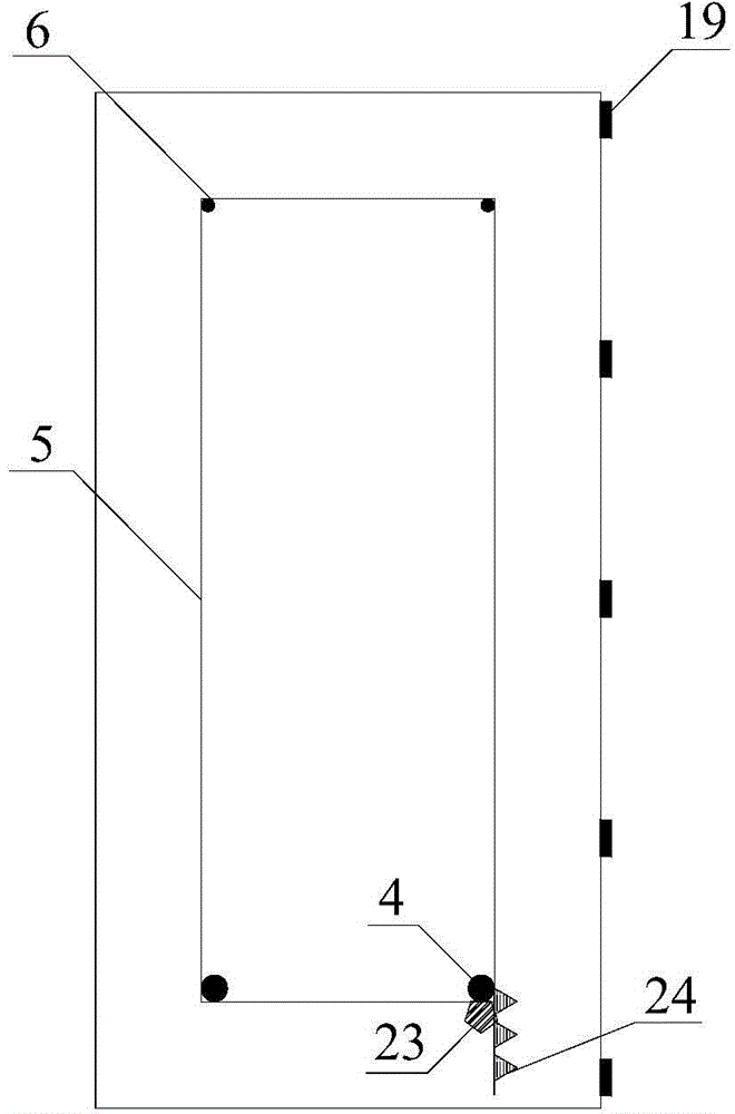
[0048] 1) Pouring reinforced concrete beams and arranging fiber grating sensors: bind the steel skeleton, and wrap a circle of fiber grating strain sensors in the circumferential direction of the longitudinal bending steel bars in the mid-span section of the beam to monitor the corrosion of the steel bars; near the mid-span section of the beam Fiber Bragg Grating strain sensors and fiber Bragg grating temperature sensors for temperature compensation are pasted axially along the longitudinal bending steel bars to monitor the stress changes of the steel bars; fiber Bragg grating pH values ​​are arranged axially along the longitudinal bending steel bars near the mid-section of the beam The sensor is used to monitor the change of PH value on the surface of the steel bar; a structural steel bar perpendicular to the vertical bending steel bar is we...

Embodiment 2

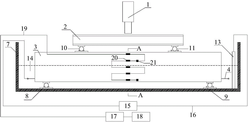
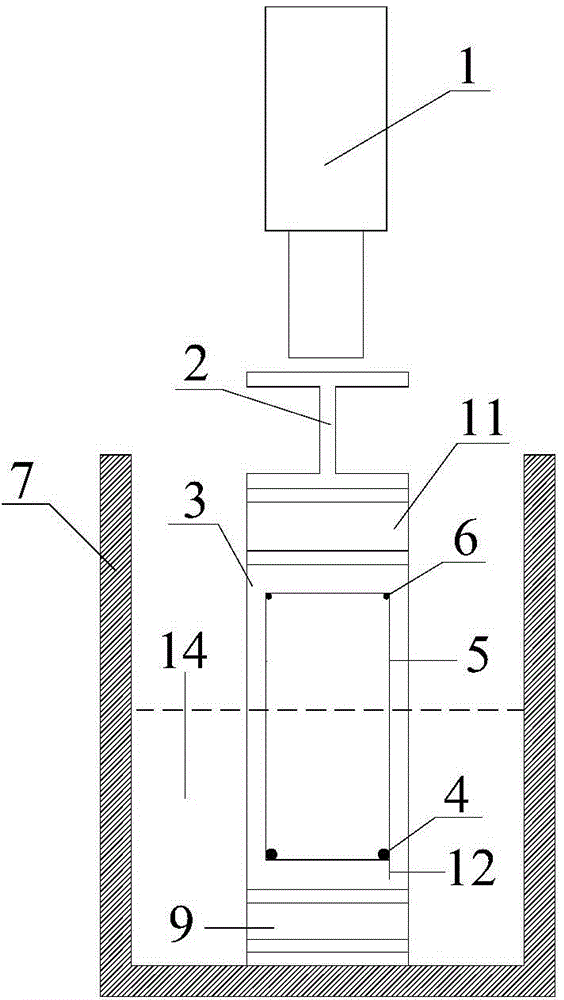
[0053] Embodiment 2 The device constructed according to the test method described in Embodiment 1 is characterized in that: the reinforced concrete beam 3 to be tested, the load distribution beam 2, the support device, the corrosion tank 4 with the upper end open, the hydraulic jack 1, the monitoring device, DC stabilized power supply 15;

[0054] A stainless steel plate 13 is placed on the inner bottom plate of the corrosion tank 7, and a 3% to 5% sodium chloride solution 14 for immersing the longitudinal bending steel bars 4 of the reinforced concrete beam 3 to be tested is housed in the corrosion tank 7;

[0055] The support device includes an upper support and a lower support, the upper support and the lower support are respectively located on the upper and lower surfaces of the reinforced concrete beam 3 to be tested, and the simply supported supports (8, 9) of the lower support are The lower backing plate is fixedly connected to the inner bottom plate of the corrosion ta...

Embodiment 3

[0065] Example 3 In this example, a reinforced concrete beam whose size is length x width x height = 2500 mm x 120 mm x 250 mm is selected as the beam for the test to explain the design idea of ​​the test device and the layout plan of the fiber grating sensor.

[0066] 1. Design and implementation of corrosion fatigue test device:

[0067] ⑴Design and manufacture of corrosion tank

[0068] The material is taken as a 5mm thick steel plate. The inner length dimension of the corrosion groove should be 250-500mm longer than the longitudinal bending steel bar, and the width direction dimension should be 100-150mm wider than the reinforced concrete beam. Here, the size of the corrosion tank is taken as length×width×height=3100mm×250mm×400mm. The inner side of the corrosion tank is painted with epoxy resin, with a thickness of about 1mm.

[0069] ⑵Design and manufacture of support device

[0070] The material is selected as steel, and the exposed parts of the supporting device ar...


PUM

PropertyMeasurementUnit
thicknessaaaaaaaaaa
coating thicknessaaaaaaaaaa

Abstract

The invention discloses a corrosion-fatigue testing method for reinforced concrete on the basis of optical-fiber sensing and a device thereof. The corrosion-fatigue testing method comprises the following steps: (1) casting a reinforced concrete beam and arranging fiber grating sensors; (2) installing the reinforced concrete beams; (3) connecting with a power supply; (4) injecting electrolyte; and (5) acquiring test data. The device constructed according to the method comprises the reinforced concrete beam to be tested, a load distributing beam, a supporting device, a corrosion groove with an opened upper end, a hydraulic jack, a monitoring device and a direct-current voltage stabilizing power supply. The corrosion-fatigue testing method and the device disclosed by the invention have the advantages that the coupling action of a corrosion medium and alternating stress is fully considered, and the environment is closer to the use environment of the reinforced concrete structure in service, so that the test data is more effective and reliable.

Description

technical field [0001] The invention belongs to electrochemistry, optics, mechanics and sensor monitoring technologies, and relates to a reinforced concrete corrosion fatigue test method based on optical fiber sensing and a device thereof. Background technique [0002] Corrosion fatigue failure of reinforced concrete structures is a phenomenon of fatigue fracture under the coupling action of alternating stress and corrosive medium. The present invention is illustrated by taking a reinforced concrete beam as an example. The corrosion fatigue deterioration mechanism of reinforced concrete beams can be expressed as follows: [0003] 1. Deterioration of reinforced concrete beams caused by chloride ions. Concrete itself is a porous structure with a large number of pores and micro-cracks. Chloride ions on the concrete surface enter the surface of the steel bar through diffusion and accumulate on the surface. It is generally believed that the diffusion of chloride ions in concr...

Claims


Application Information

Patent Timeline
Patent Type & Authority Applications(China)
IPC IPC(8): G01N17/02G01N3/56
Inventor 叶肖伟刘坦董传智
Owner ZHEJIANG UNIV
Why Eureka
Try Eureka